
Cleaning type heat-treatment oil smoke collecting and arranging equipment

A clean, oily fume technology, applied in external electrostatic separators, electrode structures, electrostatic separation, etc., can solve the problems of wasting energy, narrow application range, low dust removal efficiency, etc., and achieve high dust removal efficiency, wide application range, and oil fume removal. Efficient effect

Active Publication Date: 2008-11-05
GUANGDONG STRONG METAL TECH
View PDF1 Cites 16 Cited by
  • Summary
  • Abstract
  • Description
  • Claims
  • Application Information

AI Technical Summary

Problems solved by technology

[0004] The purpose of the present invention is to provide a clean heat treatment fume collection and discharge system in order to overcome the shortcomings of the existing oil fume purification equipment, such as narrow application range, low dust removal efficiency, and waste of energy

Method used


Image

  • Cleaning type heat-treatment oil smoke collecting and arranging equipment
  • Cleaning type heat-treatment oil smoke collecting and arranging equipment
  • Cleaning type heat-treatment oil smoke collecting and arranging equipment

Examples


specific Embodiment 1

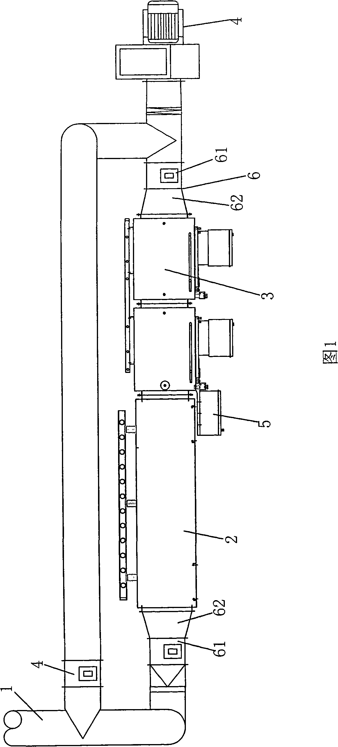
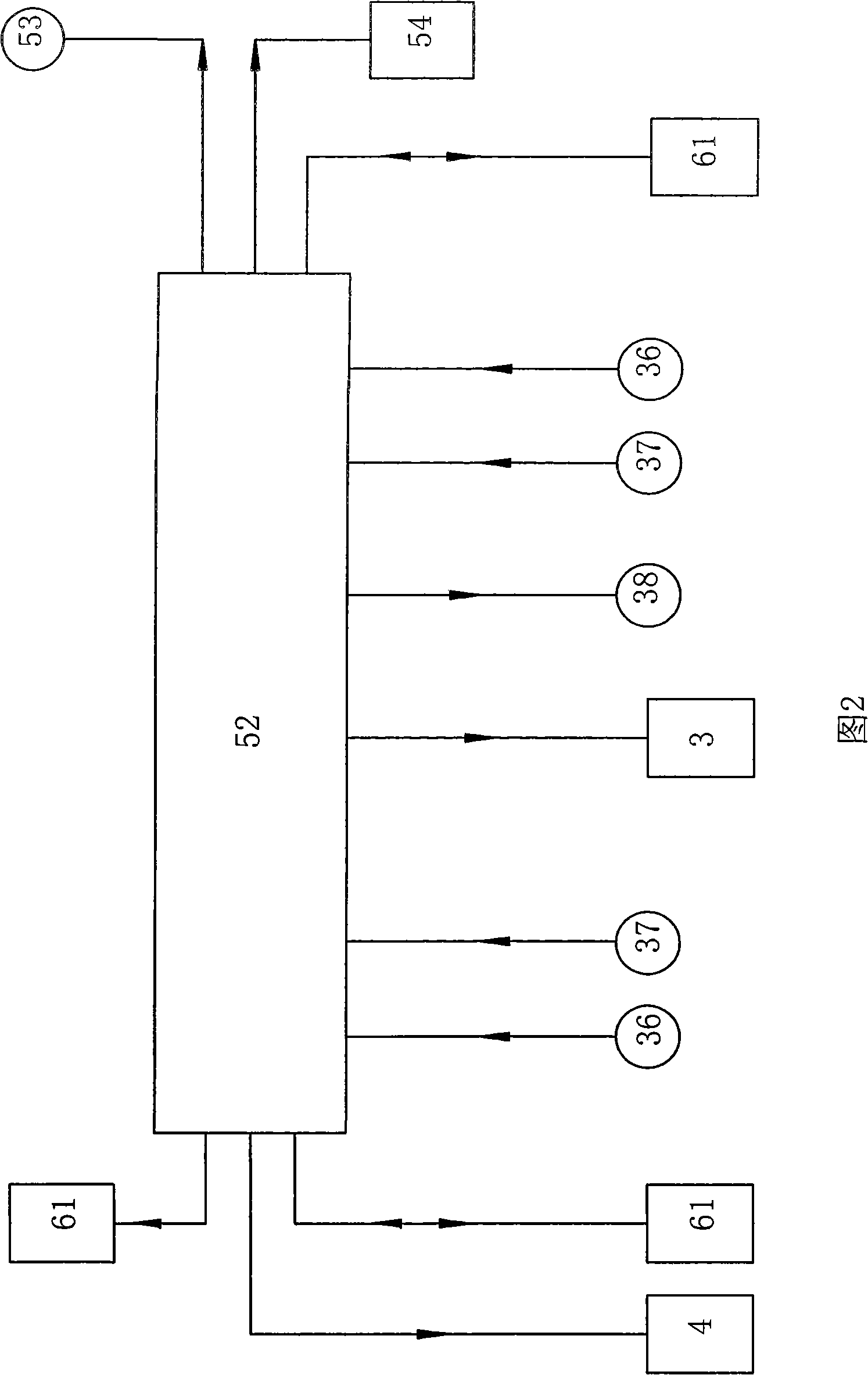
[0024] Referring to Fig. 1 and Fig. 2, this embodiment includes a fume inlet pipe 1, a heat exchange desuperheater 2, a high-voltage electrostatic degreaser 3, an exhaust fan 4 and a controller 5; the air outlet of the fume inlet pipe 1 and the heat exchange desuperheater The air inlet of 2 is connected, the heat exchange cooler 2, the high-voltage electrostatic oil fume remover 3 and the exhaust fan 4 are sequentially connected through pipelines; the controller 5 includes a PLC control circuit 52, the high-voltage electrostatic oil smoke remover 3, and the exhaust fan The signal input ends of 4 are respectively connected with the signal output ends of the PLC control circuit 52 .

[0025] In this embodiment, the air outlet of the oil fume pipe 1 is also connected to the exhaust fan 4 through a straight passage 5 with an exhaust valve, and the signal input end of the exhaust valve is connected to the signal output end of the PLC control circuit 52 . Between the fume inlet pip...

specific Embodiment 2

[0032] The characteristics of this embodiment are: the quantity of described honeycomb cylindrical electric field 32 is 1, 3, 4, 5 or 6, and one side of the casing is equipped with respectively corresponding to each honeycomb cylindrical electric field The bottom of the high-voltage solid power supply 33 and the casing are equipped with waste oil recovery pipes 34 corresponding to each honeycomb cylindrical electric field. Others are the same as in Example 1.


PUM


Abstract

The invention relates to a clean-type hot-treatment system for collecting and exhausting oil fume, which is characterized by comprising an oil fume inlet pipe (1), a temperature cooler (2) with heat exchange, an oil fume purifier (3), an exhaust fan (4) and a controller (5); the air outlet of the oil fume inlet pipe (1) is connected with the air inlet of the temperature cooler (2) with heat exchange; the air outlet of the temperature cooler (2) with heat exchange is connected with the air inlet of the oil fume purifier (3), and the air outlet of the oil fume purifier (3) is connected with the air inlet of the exhaust fan (4); the signal output end of the controller (5) is connected with the control signal input ends of both the oil fume purifier(3) and the exhaust fan (4); the signal input end of the controller (5) is connected with the signal output end of a temperature detector which is connected in the oil fume purifier (3). The heat of the oil fume is utilized by the invention, which is beneficial to save energy. The system of the invention has the advantages of wide application range, high working efficiency, high efficiency of dust collection and saving energy, which is especially applicable to the collection of oil fume particles that are smaller in particle diameter and lighter in weight.

Description

technical field [0001] The invention relates to a heat treatment fume collection and discharge system, in particular to a clean heat treatment fume collection and discharge system, which belongs to the technical field of heat treatment environmental protection devices. Background technique [0002] At present, in the process of processing workpieces by heat treatment equipment, a large amount of soot is often overflowed. These overflowing fumes can be divided into two types: one is the oil molecular clusters volatilized at high temperature, and its particle size is below 10 μm; the other is larger particle size droplets, with a particle size between 10 and 200 μm ; For droplets with a particle size between 10 and 200 μm, they are easily filtered out, and even through a long pipeline or in a certain space, they will settle down at a faster speed depending on the weight of the droplets themselves; and For oil molecular clusters with a particle size of less than 10 μm, they ar...

Claims


Application Information

Patent Timeline
Patent Type & Authority Applications(China)
IPC IPC(8): B03C3/04B03C3/34B03C3/40
Inventor 王桂茂董小虹陈志强区名结
Owner GUANGDONG STRONG METAL TECH
Learn More