
Vacuum mechanism of rubber plate vulcanization machine

A flat vulcanizing machine and vacuum technology, applied in the field of vacuum mechanism, can solve the problems of poor surface quality of finished products, complicated processing and installation, long vulcanization time of products, etc. And the effect of easy maintenance and economical

Active Publication Date: 2010-08-18
DONGYUNINGBOHYDRAULIC MACHINE INDAL
View PDF0 Cites 0 Cited by
  • Summary
  • Abstract
  • Description
  • Claims
  • Application Information

AI Technical Summary

Problems solved by technology

[0002] The vacuum mechanism of the existing rubber vulcanizer is mostly cover type, which is positioned on the circular sliding column, moves up and down on the sliding column and seals with the sliding plate, and then vacuumizes the cover to make the inside of the cover in a vacuum state. The processing and installation are relatively complicated. , the structure is also not suitable for rubber flat vulcanizing machines with a clamping force of more than 600 tons, resulting in rubber flat vulcanizing machines with a clamping force of more than 600 tons are mostly models without a vacuum system, the vulcanization time of the product is generally longer, and the quality of the finished product, especially the surface quality poor

Method used


Image

  • Vacuum mechanism of rubber plate vulcanization machine
  • Vacuum mechanism of rubber plate vulcanization machine
  • Vacuum mechanism of rubber plate vulcanization machine

Examples


Embodiment Construction

[0022] The present invention will be further described in detail below in conjunction with the accompanying drawings and embodiments.

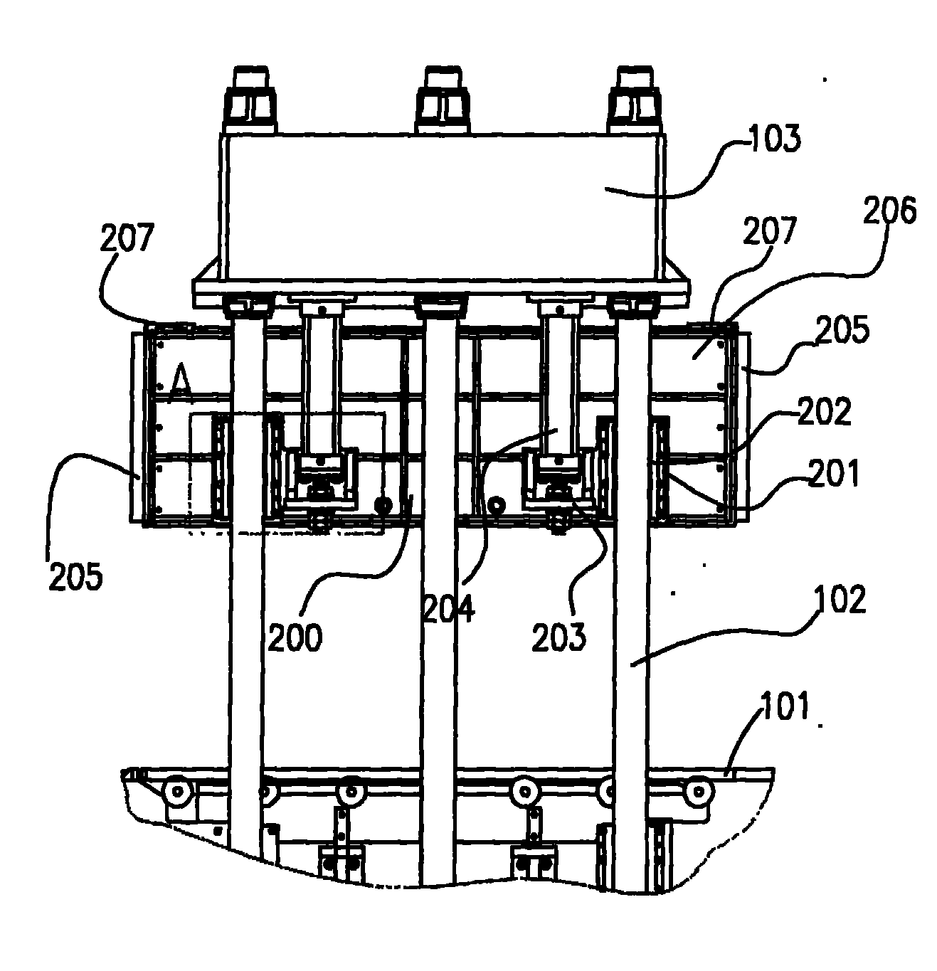
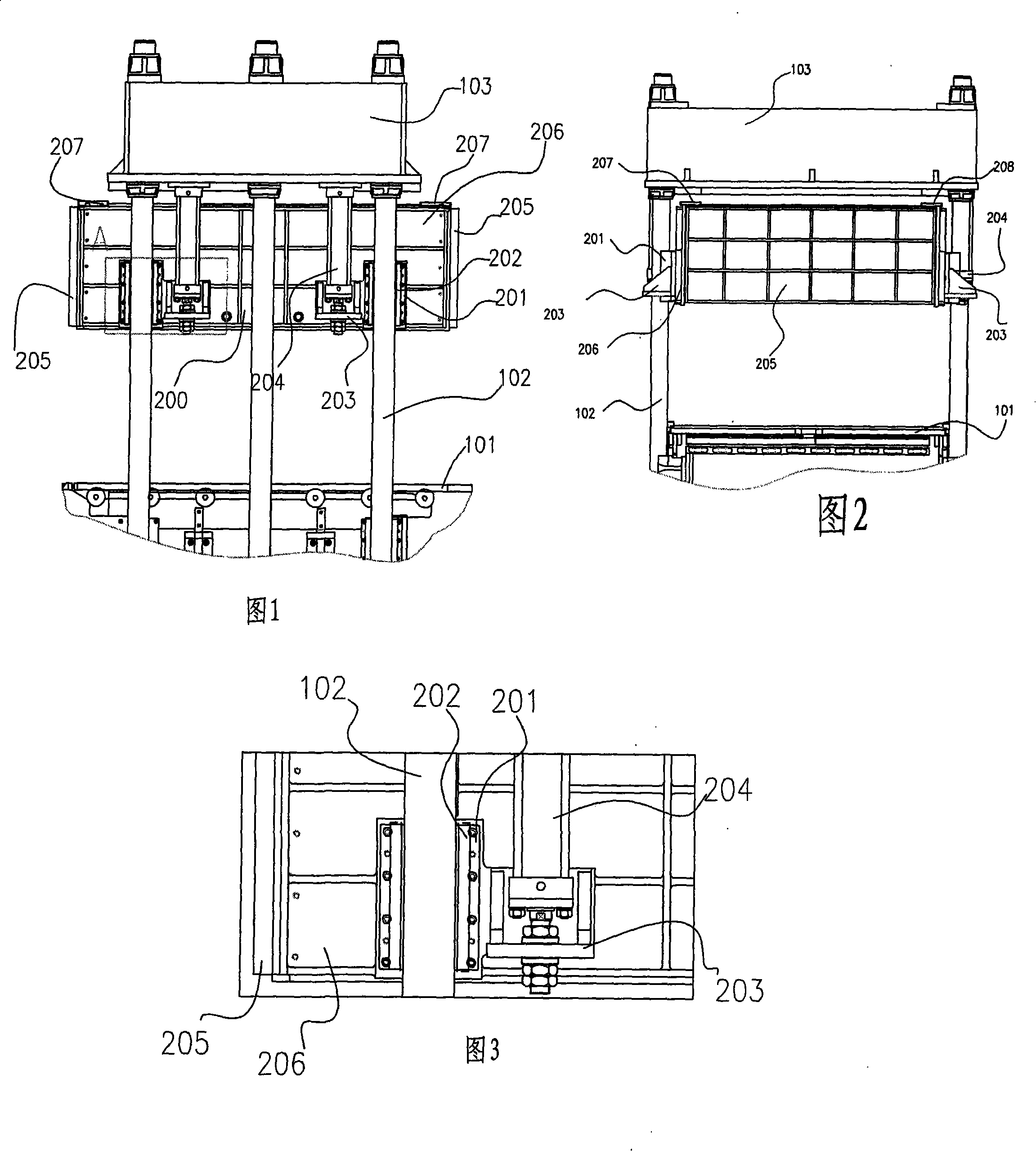
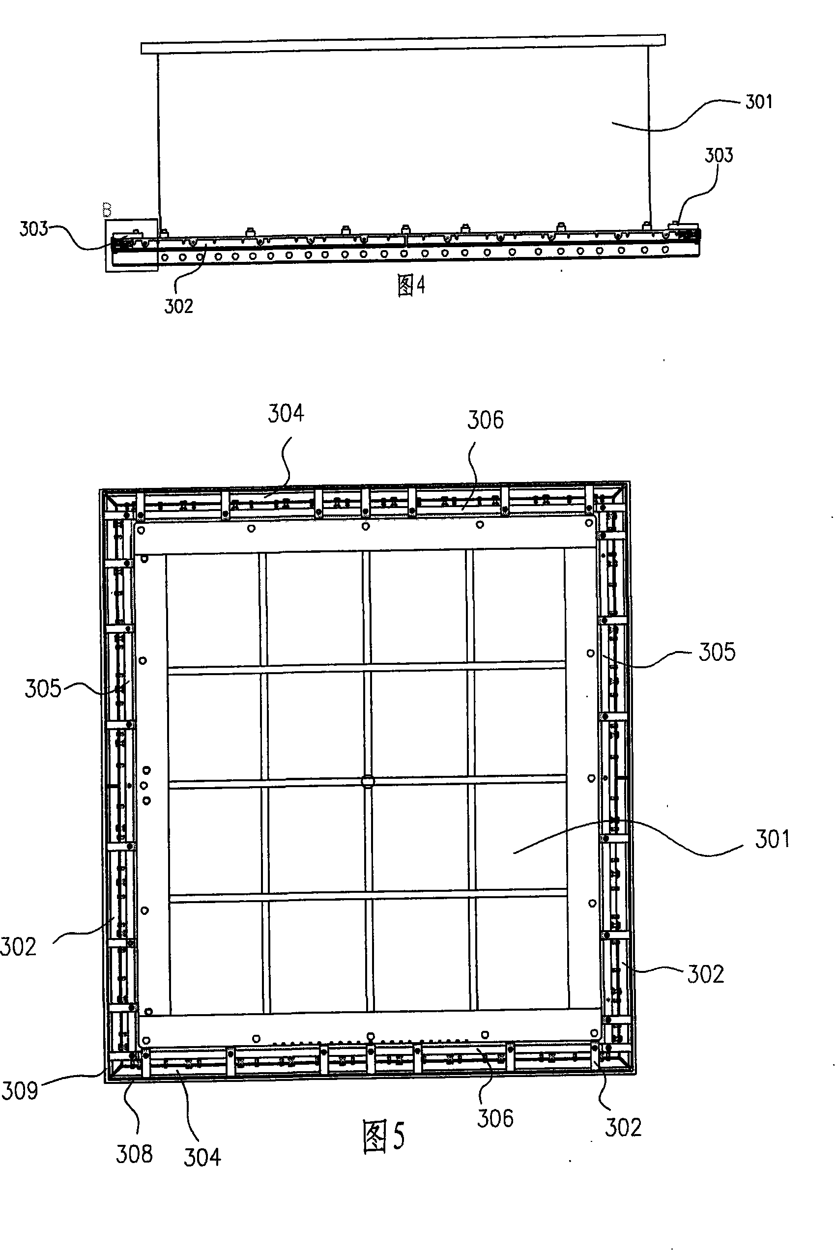
[0023] The structure of the present invention is shown in Fig. 1 to Fig. 9 . Numbers in the figure, sliding plate 101, pillar 102, top seat 103, vacuum cover 200, vacuum cover copper lining seat 201, copper lining 202, vacuum cover oil cylinder fixing frame 203, vacuum cover oil cylinder 204, vacuum cover front and rear walls 205, vacuum cover Left and right walls 206, left right-angle reinforcing plate 207, right right-angle reinforcing plate 208, sealing oil-resistant strip 209, sliding column 301, rubber strip left and right pressure plate 302, pressure plate 303, rubber strip front and rear pressure plate 304, left and right fixing blocks 305, front and rear fixing plates 306, vacuum cover leak-proof rubber strip 307, front and rear slider 308, left and right slider 309, square aluminum extruded type 310, T-shaped screw 311, T-shaped screw...


PUM


Abstract

The invention provides a vacuum mechanism used for a rubber plate vulcanization machine, comprising a sliding column which is arranged below a top base and a vacuum cover which is positioned on the sliding column and moves up and down along the sliding column; the sliding column is formed to be square by adopting the welding of steel plates; the upper part of the sliding column is fixed on the top base by fixing screws and the lower end is provided with a front sliding block, a rear sliding block, a left sliding block, a right sliding block and vacuum leakage-proof rubber strips; the vacuum cover is positioned on the sliding column; the four walls of the vacuum cover are closely attached to the sliding column; the lower end of the sliding column is provided with the front sliding block, the rear sliding block, the left sliding block, the right sliding block and the vacuum leakage-proof rubber strips; vacuum cover copper liners which are arranged at the left side and the right side of the vacuum cover are provided with copper liners which are attached to a host machine pillar and have the effect of balancing the vacuum cover; the left side and the right side of the vacuum cover arealso provided with vacuum cover cylinder fixed bases; the head of the vacuum cover cylinder is arranged on the fixed base of the vacuum cover cylinder; the tail of the vacuum cover cylinder is fixed on the top base, thus leading the vacuum cover to move up and down; the lower end of the vacuum cover is provided with hermetical oil-resistance strips; furthermore, the vacuum cover is assembled witha sliding plate so as to form a sealing space inside the vacuum cover, thus achieving the aim of vacuum pumping.

Description

technical field [0001] The invention relates to the technical field of rubber flat vulcanizing machines, in particular to a vacuum mechanism of rubber flat vulcanizing machines; it is applied to rubber flat vulcanizing machines with a mold clamping force greater than 600 tons. Background technique [0002] The vacuum mechanism of the existing rubber vulcanizer is mostly cover type, which is positioned on the circular sliding column, moves up and down on the sliding column and seals with the sliding plate, and then vacuumizes the cover to make the inside of the cover in a vacuum state. The processing and installation are relatively complicated. , the structure is also not suitable for rubber flat vulcanizing machines with a clamping force of more than 600 tons, resulting in rubber flat vulcanizing machines with a clamping force of more than 600 tons are mostly models without a vacuum system, and the vulcanization time of the product is generally longer, and the quality of the ...

Claims


Application Information

Patent Timeline
Patent Type & Authority Patents(China)
IPC IPC(8): B29C35/00B29K21/00
Inventor 杨桢堂
Owner DONGYUNINGBOHYDRAULIC MACHINE INDAL
Learn More