Composite charging condensation shock wave fire-fighting bomb

A fire-extinguishing bomb and cold-shock technology, applied in the field of fire-extinguishing, can solve the problems of poor atomization effect, destroy the fire field flow field, increase the fire field energy, etc., and achieve the effect of improving the atomization effect, reducing the surface tension, and reducing the fire field temperature.

Inactive Publication Date: 2008-11-12
UNIV OF SCI & TECH OF CHINA
View PDF3 Cites 8 Cited by
  • Summary
  • Abstract
  • Description
  • Claims
  • Application Information

AI Technical Summary

Problems solved by technology

[0003] In the prior art, there are existing examples or research reports that simply utilize water, dry powder or explosives as fire extinguishing materials for fire extinguishing bombs, such as ZL03227425.4, which uses water as a fire extinguishing material to make fire extinguishing bombs, and the internal pressure generated by the combustion of gunpowder passes through the The dense micropores on the cartridge case spray and atomize the water. This purely physical method of extinguishing the fire, due to the low internal pressure, the spraying range is limited, the atomization effect is not good, and the heat radiation is not well suppressed. The utilization rate of water Not high, fire extinguishing is slow, the fire extinguishing efficiency is not high, and it is affected by the water resources of the fire site; such as ZL200620012707.5, which uses the whole dry powder series as the fire extinguishing material to make a drop-type fire extinguishing bomb, which is thrown by a gas generator
There are deficiencies in this fire extinguishing bomb: the use of gas generators has a limited throwing range, uneven throwing, little disturbance to the flow field of the fire field, can not effectively prevent heat radiation, and is easily affected by the fire field environment, etc., and due to slow cooling, the fire field temperature The high temperature still continues, which can easily lead to re-ignition; ZL200410046754.7 uses full explosives as its fire-extinguishing material to make fire-extinguishing bombs. After the explosives explode, thermal shock waves will be generated instantly, causing strong oscillating wind speeds, and destroying the fire field flow field in a short time. Played a better role in extinguishing open flames
But this all-explosive fire extinguishing bomb can't play a good role in suppressing the heat radiation phenomenon of the fire scene, which can easily cause accidents such as personnel burns and fire spread. At the same time, it can't reduce the fire scene temperature, but increases When the fire energy is lost, when the open flame is extinguished, it is very easy to re-ignite
Moreover, the powerful shock wave will cause great damage to the protected object

Method used


Image

  • Composite charging condensation shock wave fire-fighting bomb
  • Composite charging condensation shock wave fire-fighting bomb

Examples


Embodiment 1

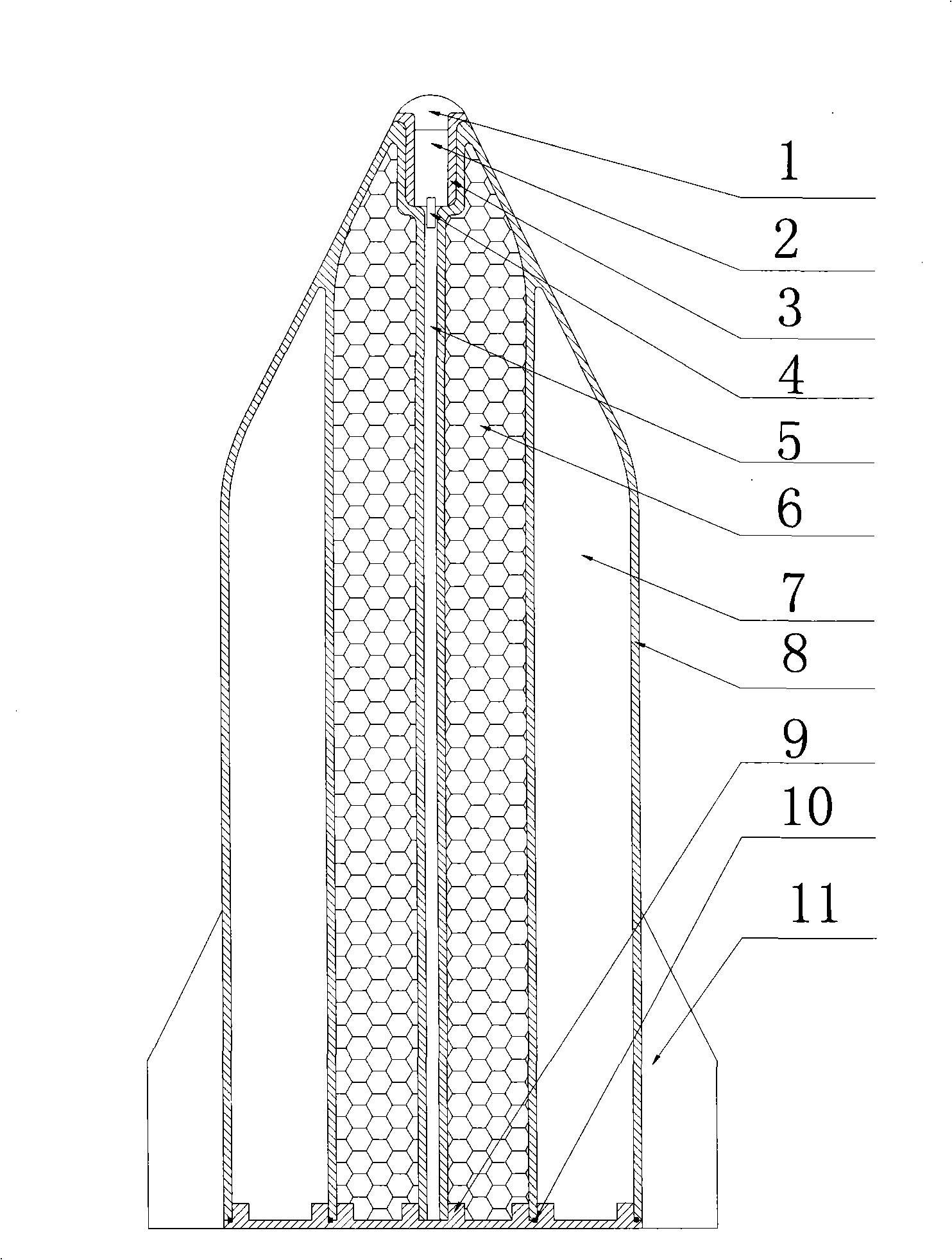
[0015] see figure 1 , the shell 8 of the composite charge structure fire extinguishing bomb of the present embodiment is formed by blow molding of flame-retardant material, and its exterior is cylindrical, and the head is conical, and the central hole is stepped with the upper part larger and the lower part smaller. The central hole is used to fill low-energy explosive spraying powder, and the large hole on the top is built with a fixed sleeve 3, which is threadedly connected with the housing 8. A fuze device 1 and a firing device 2 are sequentially arranged in the fixed sleeve 3 , and both are closely matched with the fixed sleeve 3 and fixed. The lower end of the high-safety detonator 4 is inserted in the explosion line 5 made of low-energy explosive spraying powder, and its upper end is in contact with the firing device 2 . The cavity for containing the fire extinguishing material is two annular cavities, the powder fire extinguishing material 6 is contained in the inner a...

Embodiment 2

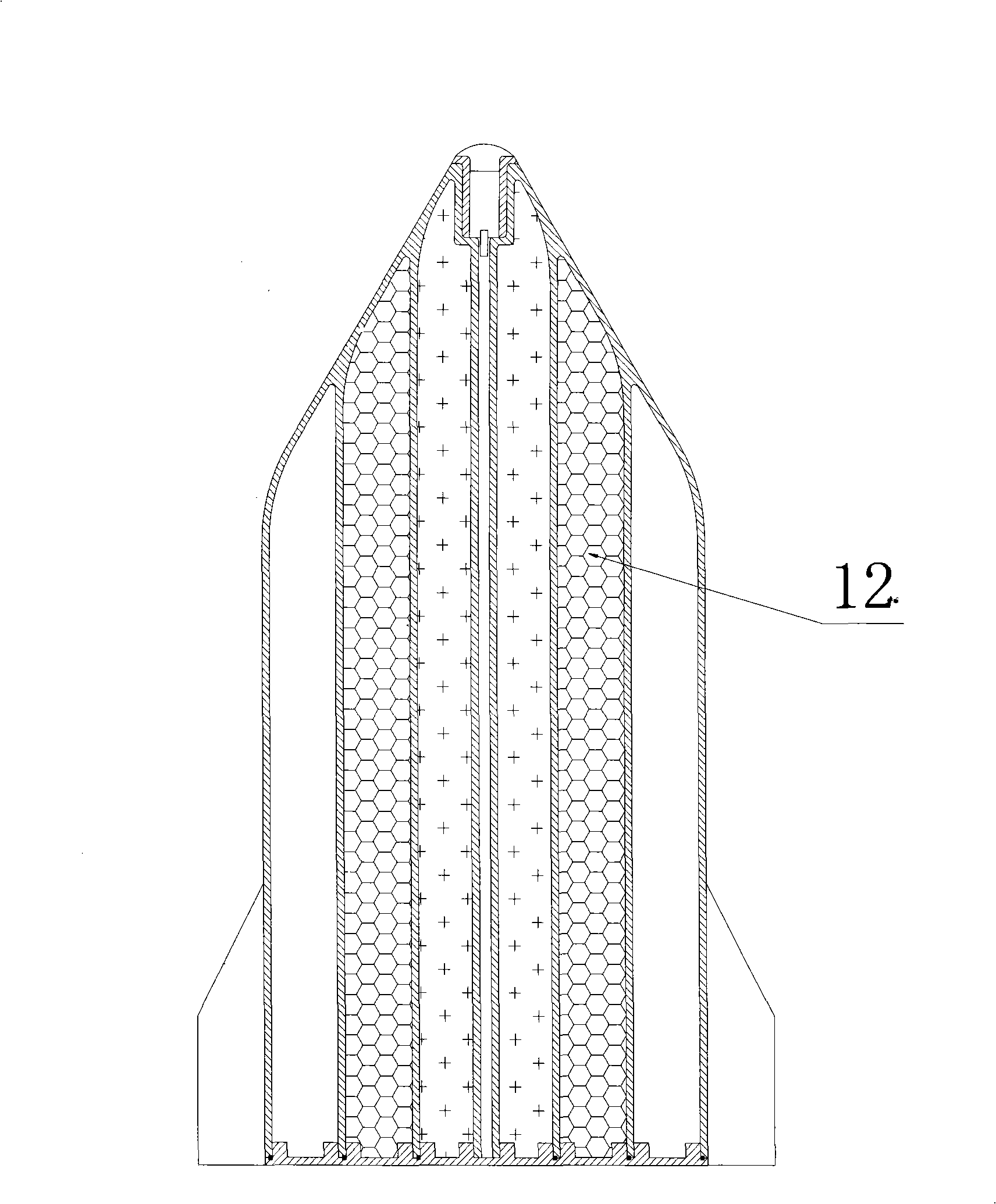
[0017] see figure 2 In this embodiment, the annular cavity containing the fire extinguishing material is divided into three, and the volume ratio between the central hole and the inner annular cavity, the middle annular cavity, and the outer annular cavity is 1:30:70:140, which can be Determine the type of charge in each annular cavity according to the nature and characteristics of the fire field, so as to extinguish the fire more effectively. For example, metal salt solution, foam fire extinguishing agent and dry powder fire extinguishing agent are respectively contained in the three cavities. Compared with Embodiment 1, this embodiment adds a middle annular cavity 12, and the rest of the structure is substantially the same as that of the embodiment.

[0018] In order to demonstrate the actual use effect of the present invention, adopt such as figure 1 The cold shock wave fire extinguishing bomb with double-layer composite charge structure shown in the fire extinguishing t...


PUM


Abstract

The invention relates to a fire extinguishing technique and particularly relates to a manufacturing technique of a fire extinguishing bomb which can be released in an airborne manner or used for cannonball launching. The fire extinguishing bomb comprises a cylinder shell provided with a conical warhead; the cylinder shell is provided with a central hole used for placing a low-energy initiating explosive, a fusing device and a firing gear, and a cavity used for holding extinguishing materials; the cavity used for holding extinguishing materials is two or more than two annular- shaped, wherein the liquid extinguishing material is placed in at least one annular-shaped space and powder extinguishing material or foam extinguishing agent is placed in another annular-shaped space; each annular-shaped space is respectively sealed; the ratio of the volume of the central hole to the total volume of the annular-shaped spaces holding the extinguishing materials is controlled at a range from 1-500 to 2000. The extinguishing bomb of the invention is provided with a multi-layer cavity structure in the shell, which can determine the type of the drug placed in different cavities according to the nature and characteristic of the fire scene, combines the physical fire extinguishment and the chemical fire extinguishment, and can put out a fire quickly, moreover, the after-burning does not happen easily, and thus having the advantages of high efficiency, good safety, strong flexibility and low cost.

Description

technical field [0001] The invention relates to a fire extinguishing technology, in particular to a production technology of a fire extinguishing bomb that can be dropped on an aircraft, launched by a rocket or launched by a cannon. Background technique [0002] When the fire is uncontrollable, it will bring great destructiveness and disasters, and pose a huge threat to life, property and the ecological environment. According to statistics on fires published worldwide, in 1995-1996 and 2000, the total number of fires in the United States, Europe, and China was about 12 million, resulting in 13,000 deaths and at least 170,000 injuries. The direct economic losses were respectively 12.9 billion US dollars, 23 billion US dollars and 1.5 billion RMB. With the continuous acceleration of industrialization and urbanization in our country, the development of high-rise buildings is changing with each passing day, but high-rise fire accidents are also increasing. Due to the lack of ef...

Claims


Application Information

Patent Timeline
Patent Type & Authority Applications(China)
IPC IPC(8): F42B12/52
Inventor 沈兆武蒋耀港樊自建马宏昊
Owner UNIV OF SCI & TECH OF CHINA
Why Eureka
Try Eureka