
Semiconductor device and manufacturing method thereof

A manufacturing method and semiconductor technology, which are applied in semiconductor/solid-state device manufacturing, semiconductor devices, electric solid-state devices, etc., can solve the problem that the size of the device is difficult to reduce, and achieve the advantages of improving the withstand voltage characteristics, suppressing the expansion, and reducing the number of masks. Effect

Inactive Publication Date: 2008-11-12
SANYO ELECTRIC CO LTD +1
View PDF1 Cites 4 Cited by
  • Summary
  • Abstract
  • Description
  • Claims
  • Application Information

AI Technical Summary

Problems solved by technology

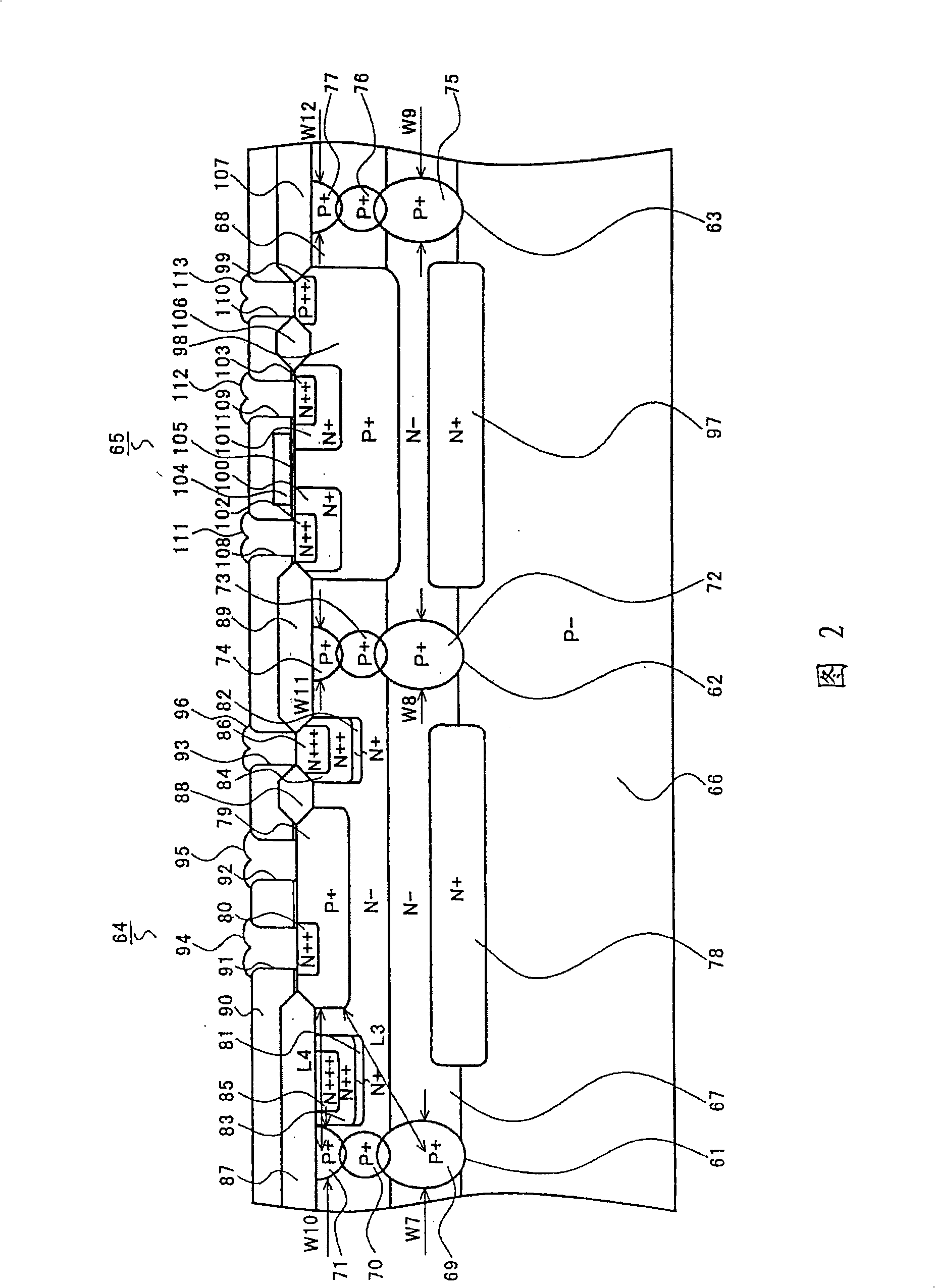
In this case, the diffusion width W26 of the buried layer 307 and the diffusion width W27 of the diffusion layer 308 become wider, and there is a problem that it is difficult to reduce the device size of the NPN transistors 301 and 302.

Method used


Image

  • Semiconductor device and manufacturing method thereof
  • Semiconductor device and manufacturing method thereof
  • Semiconductor device and manufacturing method thereof

Examples


Embodiment Construction

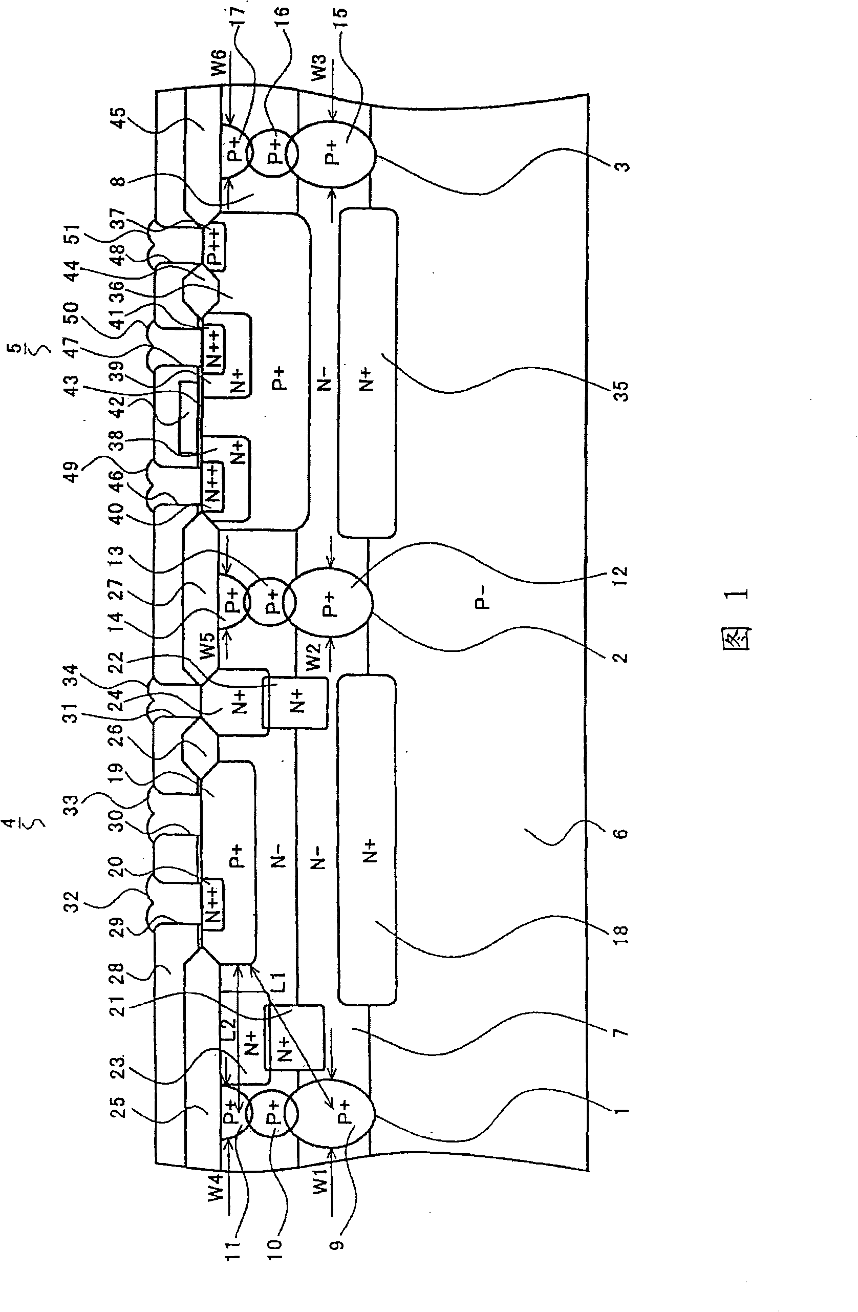
[0061] Next, a semiconductor device according to a first embodiment of the present invention will be described with reference to FIG. 1 .

[0062] As shown in FIG. 1, isolation regions (hereinafter referred to as ISOs) 1 to 3 are formed in a grid pattern over the entire IC, and various semiconductor elements are formed in island regions (hereinafter referred to as islands) surrounded by the ISOs. As shown in the figure, an NPN transistor 4 is formed on one island, and an N-channel MOS transistor 5 is formed on the other island.

[0063] First, as shown in the figure, ISOs 1-3 penetrate the first and second N-type epitaxial layers (hereinafter referred to as EPI) 7, 8 on the P-type single crystal silicon substrate 6, and are divided into a plurality of islands. ISO 1 to 3 consist of three snowman-shaped diffusion layers. For example, ISOs 1 to 3 are composed of P-type buried diffusion layers (hereinafter referred to as buried layers) 9 , 10 , 12 , 13 , 15 , and 16 and P-type d...


PUM


Abstract

The invention relates to a semiconductor device and a manufacturing method thereof, to solve the problem in current semiconductor devices that a forming region of ISO is difficult to become narrow caused by lateral diffusion width extension of a P-type buried layer that forms ISO. In the semiconductor device of the invention, double layered EPIs (7) and (8) are formed on a P-substrate (6); ISOs (1), (2) and (3) are formed in the substrate (6) and the EPIs (7) and (8), which are divided into a plurality of islands. ISO (1) is formed by connecting L-ISO (9), M0ISO (10) and U-ISO (11). M-ISO (10) is disposed between L-ISO (9) and U-ISO (11), such that a lateral diffusion width (W1) of L-ISO (9) is reduced. With the structure, a forming region of ISO (1) becomes narrow.

Description

technical field [0001] The present invention relates to a semiconductor device and its manufacturing method. Background technique [0002] As an example of a conventional semiconductor device, the following structure of the NPN transistor 281 is known. As shown in FIG. 25 , an N-type epitaxial layer (hereinafter referred to as EPI) 283 is formed on a P-type semiconductor substrate 282 . In EPI 283 , P-type buried diffusion layers (hereinafter referred to as buried layers) 284 and 285 diffused upward and downward from the surface of substrate 282 , and P-type diffusion layers 286 and 287 diffused from the surface of EPI 283 are formed. Then, the EPI 283 is divided into a plurality of island regions (hereinafter referred to as islands) by isolation regions (hereinafter referred to as ISO) 288 and 289 formed by connecting the buried layers 284 and 285 and the diffusion layers 286 and 287 . In one island, for example, an NPN transistor 281 is formed. The NPN transistor 281 is...

Claims


Application Information

Patent Timeline
IPC IPC(8): H01L27/04H01L27/06H01L21/822H01L21/8249H01L21/76
Inventor 相马充畑博嗣天辰芳正
Owner SANYO ELECTRIC CO LTD
Learn More