Beam catching device for a processing machine

A capture device, processing machine technology, applied in metal processing, metal processing equipment, manufacturing tools, etc., can solve problems affecting cutting beams, etc., and achieve the effects of easy exclusion, direct collision prevention, and adhesion prevention

Inactive Publication Date: 2008-11-12
TRUMPF WERKZEUGMASCHINEN GMBH & CO KG
View PDF2 Cites 3 Cited by
  • Summary
  • Abstract
  • Description
  • Claims
  • Application Information

AI Technical Summary

Problems solved by technology

In addition, the cutting beam is influenced by beam reflections due to spatters, sparks or debris that have not yet been removed

Method used


Image

  • Beam catching device for a processing machine
  • Beam catching device for a processing machine
  • Beam catching device for a processing machine

Examples


Embodiment Construction

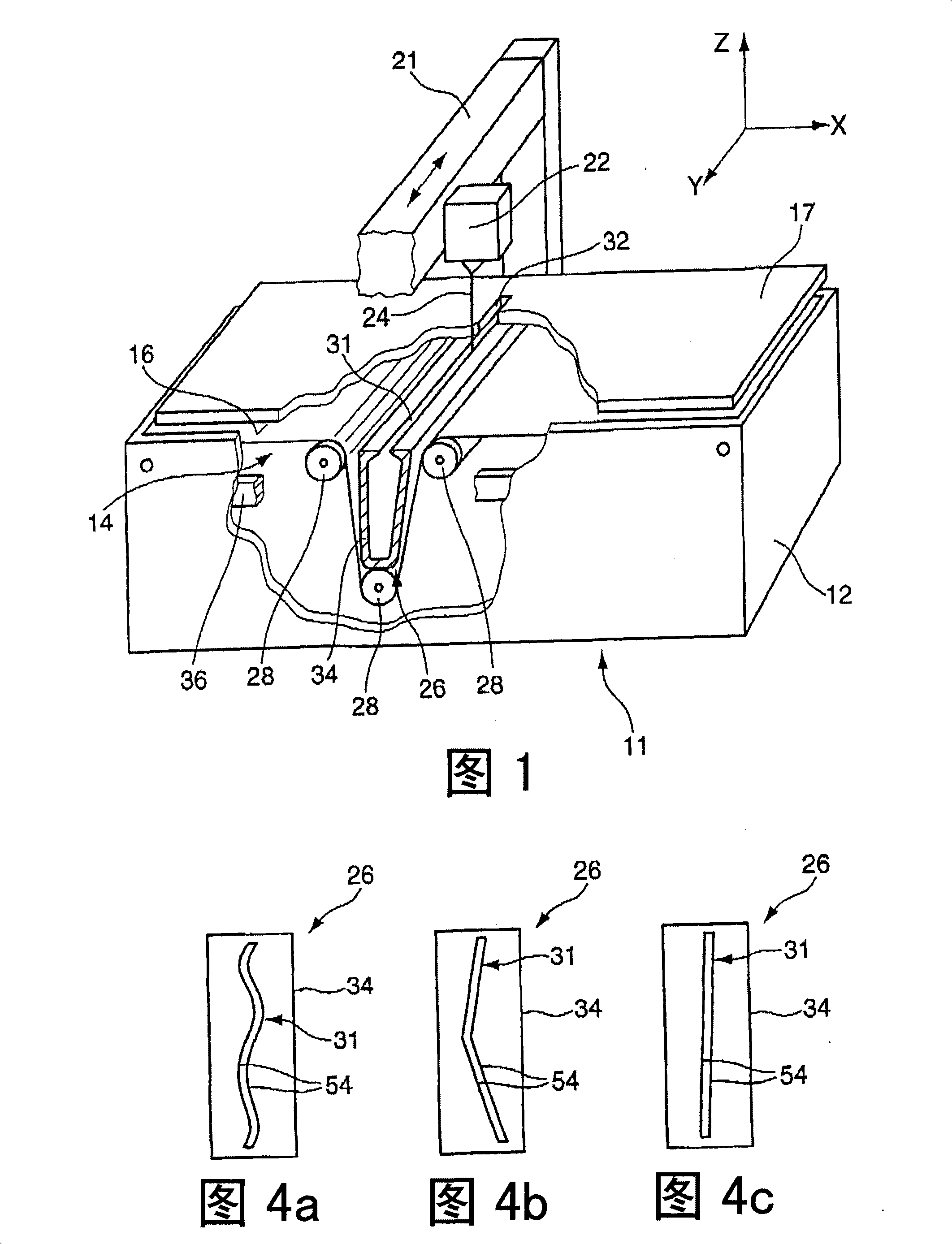
[0048] The processing machine 11 is shown in perspective in FIG. 1 . The processing machine 11 is preferably designed as a laser cutting machine. Alternatively, plasma cutters or flame cutters can also be formed. The machine bed 12 includes a workpiece support 14 which is formed, for example according to FIG. 1 , by a support belt 16 which is held stationary in the machine bed 12 . In an alternative embodiment, the carrier belt can also be driven movably and can additionally fulfill a transport function. The cutting head 22 is movable in the Y direction via the linear axis 21 and forms the working area of ​​the cutting head 22 . Additionally, a rectilinear axis can be provided that can traverse back and forth with respect to the X direction. Furthermore, it is also possible to provide linear axes which can be moved vertically. A cutting beam 24 is directed from the cutting head 22 onto the workpiece 17 in order to carry out machining.

[0049] On the underside of the work...


PUM


Abstract

The invention relates to a beam catching device for a beam cutting processing machine comprising a housing (34) provided with an opening (31) arranged in front of a cutting beam (24), wherein, during processing a workpiece (17), the cutting beam (24) exits from the workpiece (17) lower side and enters through the opening (31) a beam trap chamber (35) arranged in the housing (34), at least one nozzle (63, 76) is positioned on at least one wall section (56, 44, 46, 47) of the housing (34) and injects into the beam trap chamber (35) a fluid jet (64) in the form of a free jet in such a way that said fluid jet (64) crosses the cutting beam (24).

Description

technical field [0001] The invention relates to a beam capture device for a processing machine according to the preamble of claim 1 . Background technique [0002] Patent Publication JP 4-91884 discloses a processing machine in which a workpiece is placed on a workpiece support for processing. The workpiece is moved transversely to the machining direction of the cutting head via the workpiece support. To process a workpiece, a cutting beam is directed onto the workpiece, which is emitted from below during the machining of the workpiece. A housing having an opening through which the cutting beam emerging at the underside enters the housing is assigned to the emission region as a beam capture device. The opening and housing extend along the working area of ​​the cutting head. [0003] This cutting beam capture device has the disadvantage that the cutting beam, in particular the laser beam or the flame cutting jet, which is received by the housing and emerges from the workpi...

Claims


Application Information

Patent Timeline
Patent Type & Authority Applications(China)
IPC IPC(8): B23K26/42B23K26/14B26F3/00B23K7/10
CPCB23K26/425B26F3/008B23K26/1405B23K26/38B23K26/142B23K26/704
Inventor D·加尔夫
Owner TRUMPF WERKZEUGMASCHINEN GMBH & CO KG
Why Eureka
Try Eureka