Electromagentic furnace provided with magnetic induction temperature measuring equipment

A technology of temperature measuring device and induction cooker, which is applied in the field of induction cooker, can solve problems such as increased number of power outages, impact of control system, limitation of temperature detection, etc., and achieves the effects of improving automation, easy implementation, and widening applications

Inactive Publication Date: 2008-11-19
叶小舟 +1
View PDF1 Cites 22 Cited by
  • Summary
  • Abstract
  • Description
  • Claims
  • Application Information

AI Technical Summary

Problems solved by technology

Among them, the contact temperature detection method uses the temperature at the bottom of the electromagnetic cooker to conduct temperature control to the heat-sensitive element through the platen of the induction cooker. It is difficult to ensure accurate and timely transmission to the heat-sensitive element, especially at a specific temperature point, the heat-sensitive element cannot get the signal accurately and timely, and it is difficult to realize the accurate and automatic control of the temperature of the induction cooker during the cooking process
Therefore, this technical solution has the following defects: (1) in order to ensure the normal detection of the magnetic sensor, the power supply of the heating coil must be often disconnected, which is not conducive to the normal heating work of the induction cooker; (2) the heating coil is set to be disconnected for the first time during the heating process The time of the power supply will vary depending on the amount of food to be heated. Therefore, it is difficult to set a more suitable time point for all situations. For the case where the power-off time point is set early, the number of power-off times will increase and the detection time will increase. If it is too long, it will affect the heating efficiency; (3) The frequent switching action of the high-power tube or power module of the induction cooker will impact the control system, which will affect the service life of the control system; (4) It is difficult to detect multiple temperature points: Because different cooking procedures require different temperature points to be controlled, that is, not all cooking procedures require reaching the Curie point to work, and this detection method can only detect the Curie point temperature of the temperature-sensing magnetic steel, but cannot detect multiple points. Therefore, it is impossible to flexibly and accurately control the multi-point temperature required in the cooking process of the induction cooker, and the temperature detection is still limited

Method used


Image

  • Electromagentic furnace provided with magnetic induction temperature measuring equipment
  • Electromagentic furnace provided with magnetic induction temperature measuring equipment
  • Electromagentic furnace provided with magnetic induction temperature measuring equipment

Examples


Embodiment 1

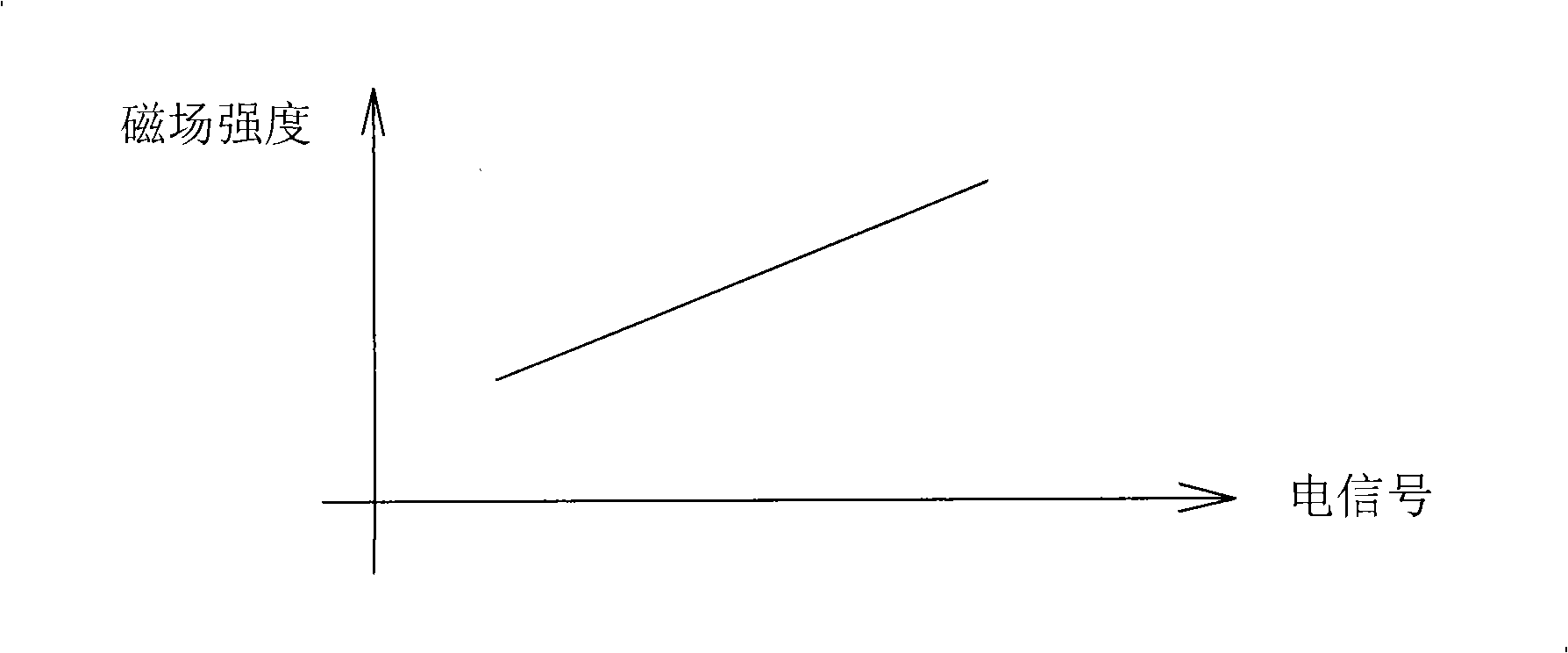
[0036] Such as Figure 4 , Figure 5 , Figure 6 The shown induction cooker provided with a magnetic induction temperature measuring device is one of embodiments of the present invention, comprising an induction cooker shell 2, an induction cooker platen 3, a heating coil 4 and a control circuit, the control circuit comprising a control board 1 and a drive board 8, heating The center of the coil 4 is provided with a bracket 5 on which a thermistor 7 is mounted. There is also a temperature-measuring induction coil 6 below the induction cooker table 3, which is used to convert the magnetic signal generated by the magnetic temperature sensing element 10 above the induction cooker table 3 at a set temperature point into an electrical signal and output it. The coil 6 is matched with the heating coil 4 and can generate an induction electric signal. The temperature-measuring induction coil 6 is located near the heating coil 4 and the magnetic temperature-sensing element 10, in an ...

Embodiment 2

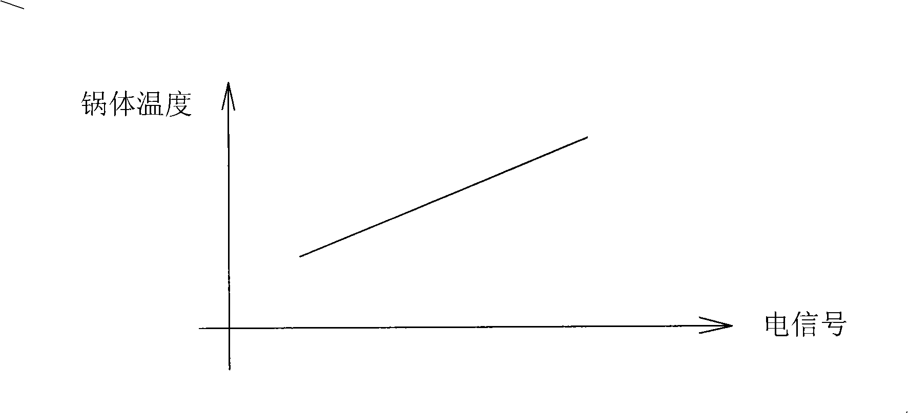
[0041] Such as Figure 7 , Figure 8 , Figure 9 , Figure 10 , Figure 11 The electromagnetic oven shown with a magnetic induction temperature measuring device is the second embodiment of the present invention. The difference from Embodiment 1 is that the temperature measuring induction coil 6 is located in the center of the heating coil 4, and the magnetic temperature sensing element 10 adopts thermosensitive ferrite Material, when the induction cooker is working, under the same magnetic field strength, the magnetic flux passing through the temperature measuring induction coil 6 is the largest. The temperature measuring induction coil 6 and the thermistor 7 are fixed below the induction cooker platen 3 by the bracket 5 . The bracket 5 is a ladder-shaped frame with a longitudinal section, the thermistor 7 is fixed on the higher frame, and the temperature-measuring induction coil 6 is fixed on the lower frame. The magnetic temperature-sensing element 10 is centrally fixed...

Embodiment 3

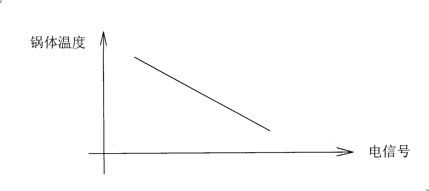
[0047] Such as Figure 12 , Figure 13 , Figure 14 The shown electromagnetic cooker provided with a temperature measuring device is the third embodiment of the present invention. The difference from Embodiment 2 is that the magnetic temperature sensing element 10 is a temperature-sensitive magnetic steel made of nanocrystalline material, and the electromagnetic cooker is equipped with a specific electromagnetic cooker 9 In use, the magnetic temperature sensing element 10 is directly located at the bottom of the electromagnetic cooker 9 with a double-layer structure for supporting use. The electromagnetic cooker 9 has an outer shell 91 and an inner shell 92. The heat of the electromagnetic cooker with this structure is not easy to lose, and the heat preservation Better results. The magnetic temperature sensing element 10 is located between the two layers of shells, that is, the outer shell 91 at the bottom of the electromagnetic cooker 9 is directly in contact with the induc...


PUM


Abstract

The invention discloses an induction cooker provided with a magnetic induction temperature measuring device, comprising an induction cooker shell, an induction cooker bedplate, a heating coil and a control circuit. The induction cooker is characterized in that a position where a lower side of the induction cooker bedplate is adjacent to the heating coil is also provided with a temperature measuring induction coil which is used for converting a magnetic signal generated by a magnetic temperature induction element which is arranged on the induction cooker bedplate at a set temperature point into an electric signal to output, the induction cooker control circuit is also provided with a temperature measuring circuit which is mainly formed by a temperature measuring induction coil and an electric signal discriminating circuit, wherein the temperature measuring induction coil is connected with the electric signal discriminating circuit, and the electric signal discriminating circuit is again connected with an output control circuit so that a control program of the induction cooker can change correspondingly. The temperature of an electromagnetic pot is detected by adopting non-contact way, thereby realizing automatic, flexible and correct control of multipoint temperature of the induction cooker in the process of cooking.

Description

technical field [0001] The invention relates to an electromagnetic cooker, in particular to an electromagnetic cooker provided with a magnetic induction temperature measuring device. Background technique [0002] An induction cooker is a household appliance that uses an electromagnetic field to directly heat an electromagnetic cooker made of ferromagnetic materials as a load for cooking. In the prior art, the temperature control process of the induction cooker includes a contact temperature detection method and a non-contact temperature detection method. Among them, the contact temperature detection method uses the temperature at the bottom of the electromagnetic cooker to conduct temperature control to the heat-sensitive element through the platen of the induction cooker. It is difficult to ensure accurate and timely transmission to the thermal element, especially at a specific temperature point, the thermal element can not get the signal accurately and timely, and it is d...

Claims


Application Information

Patent Timeline
Patent Type & Authority Applications(China)
IPC IPC(8): F24C7/08
CPCH05B6/062
Inventor 叶小舟林卫文刘劲旋彭霭钳
Owner 叶小舟
Why Eureka
Try Eureka