
Electro-optical device, method for driving the same, and electronic machine

An electro-optical device, liquid crystal driving technology, applied in electrical components, color TV parts, optics, etc., can solve the problems of difficult driving frequency and lighting period setting, not taking into account color disorder, shortening the liquid crystal voltage holding period, etc.

Inactive Publication Date: 2008-11-19
SEIKO EPSON CORP
View PDF2 Cites 1 Cited by
  • Summary
  • Abstract
  • Description
  • Claims
  • Application Information

AI Technical Summary

Problems solved by technology

However, in the technology described in the above-mentioned Patent Document 1, in order to further increase the switching frequency of the light source color, it is necessary to shorten the voltage holding period of the liquid crystal, so it is difficult to optimally set both the driving frequency and the light emitting period.
In addition, in the technology described in Patent Document 2, color breakup caused by color sequential driving is not taken into consideration.

Method used


Image

  • Electro-optical device, method for driving the same, and electronic machine
  • Electro-optical device, method for driving the same, and electronic machine
  • Electro-optical device, method for driving the same, and electronic machine

Examples


no. 1 Embodiment approach

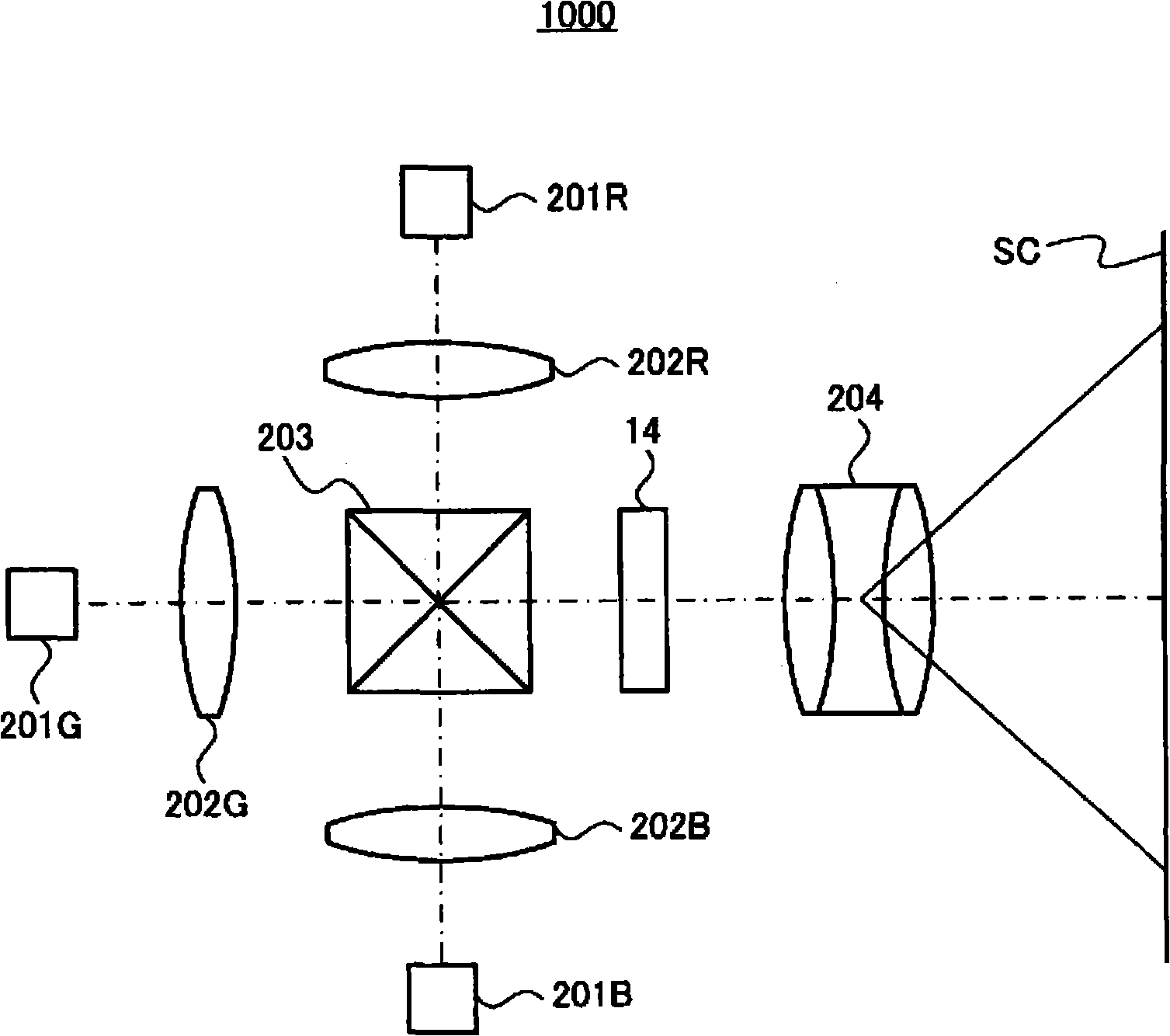
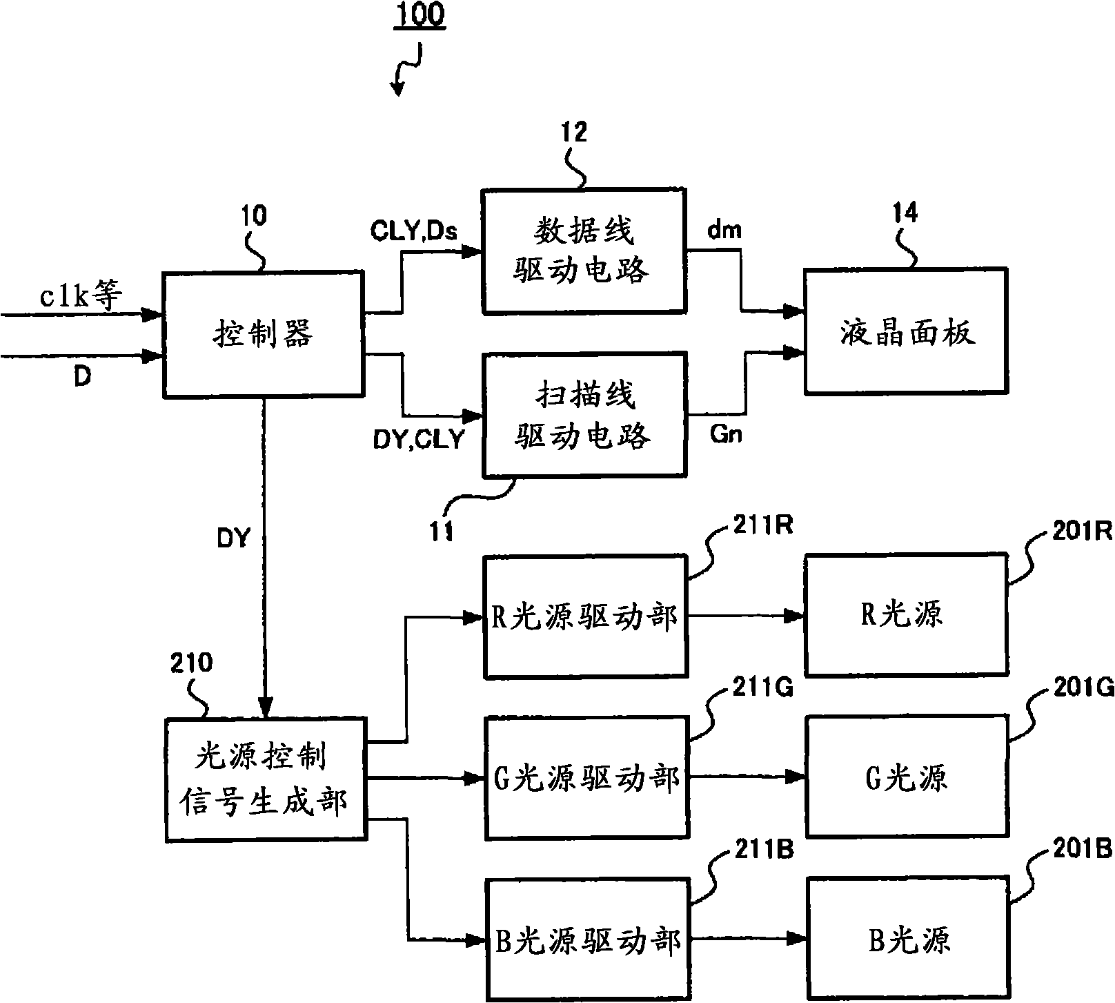
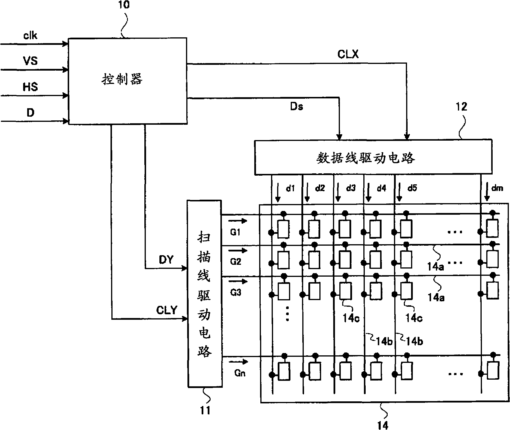
[0061] In the first embodiment, the switching of the light source color is controlled so that the switching period of the light source color is shorter than the period in which the liquid crystal 14g of the pixel 14c constitutes a gradation. That is, in the first embodiment, subfields using the same light source color are not continued, but are switched to subfields of different light source colors before temporally forming gradations. This corresponds to the case where gray scales are formed by making the light source emit light at an appropriate timing while suppressing the driving of the liquid crystal panel 14 as much as possible. As a result, color breakup due to color sequential driving can be suppressed, and good color rendering and gradation characteristics can be realized.

[0062] In addition, such switching control of light source colors is mainly performed by the light source control signal generation unit 210 in the above-mentioned drive circuit 100 . Specificall...

no. 2 Embodiment approach

[0074] Next, the light source control method of the second embodiment will be described. In the second embodiment, like the above-mentioned first embodiment, the switching of the light source color is controlled so that the switching cycle of the light source color is shorter than the cycle in which the liquid crystal 14g constitutes a gradation. However, the second embodiment is different from the first embodiment in that the switching period of the light source color is changed according to the input image signal D. Specifically, in the second embodiment, the average gradation value for each color is obtained from the image signal D, and the switching period of the light source color is changed based on the average gradation value. That is, in the second embodiment, the switching period of the light source color is changed according to the color tendency in the image. In this way, it is possible to effectively suppress the display deterioration caused by the non-response of...


PUM


Abstract

The invention provides an electro-optical device and a drive method thereof and an electronic device. The electro-optical device can inhibit the color splitting caused by the drive of the color order to achieve the great color development and gray-tone response. The electro-optical device uses the color order drive way of light source for three light sources for processing the full-color development. The liquid crystal drive unit that divides on a temporal axis one field into subfields and that, during the subfields, applies either an on-voltage or an off-voltage to picture elements of a liquid crystal display in accordance with gradation of the picture elements during the one field. A light source control unit sequentially switches the three light sources, and switches at least two of the three light sources at a switching period that is shorter than a time duration required to exhibit, in the picture elements during the one field, gradation of each color corresponding to each of the at least two of the three light sources. The invention controls the shift of the light source which makes the shifting period of the light source is shorter than the liquor crystal composing grey in the pixels. According to the electro-optical device, the invention can inhibit the color splitting caused by the drive of the color order without reducing the brightness to achieve the great color development and gray-tone response.

Description

technical field [0001] The present invention relates to an electro-optic device driven by a so-called color sequential driving method, a driving method thereof, and an electronic device. Background technique [0002] Conventionally, there are known projectors and the like that use solid-state light sources such as LDs and LEDs, and are driven by a so-called color sequential driving method (field sequential method). This color sequential driving method is a driving method for displaying an image by switching the light source color in time division, and the individual color components projected on the retina are mixed by the integration function of the human eye to perceive full color. As is well known, in this driving method, when the eyes are moved or the like, the color components cannot be mixed, so a color break phenomenon occurs. [0003] Here, when color sequential driving is performed in a single-panel liquid crystal projector, due to the influence of the response tim...

Claims


Application Information

Patent Timeline
Patent Type & Authority Applications(China)
IPC IPC(8): G09G3/36G09G3/34
CPCG09G3/3648G02F2001/133622G09G2310/0235H04N9/3114H04N9/3155G09G3/2022G09G3/3413G02F1/133622G02F1/133G09G3/20G09G3/36
Inventor 丰冈隆史保坂宏行
Owner SEIKO EPSON CORP
Learn More