Microbiological fuel cell pile

A fuel cell stack and fuel cell technology, applied in the field of environment and new energy, can solve the problems of high cost, unfavorable expansion and amplification, etc., and achieve the effects of small footprint, high output power density, and low cost

Active Publication Date: 2008-12-03
GUANGDONG INST OF ECO ENVIRONMENT & SOIL SCI
View PDF4 Cites 21 Cited by
  • Summary
  • Abstract
  • Description
  • Claims
  • Application Information

AI Technical Summary

Problems solved by technology

[0009] The purpose of the present invention is to overcome the shortcomings of the existing microbial fuel cell structure and operation mode that are not conducive to expansion and amplification and high cost, and to provide a microbial fuel cell stack, which has the advantages of easy expansion, unified feeding and discharging, Compact structure, low cost, high output power density, good COD (chemical oxygen demand) removal effect, etc.

Method used


Image

  • Microbiological fuel cell pile
  • Microbiological fuel cell pile
  • Microbiological fuel cell pile

Examples


Embodiment 1

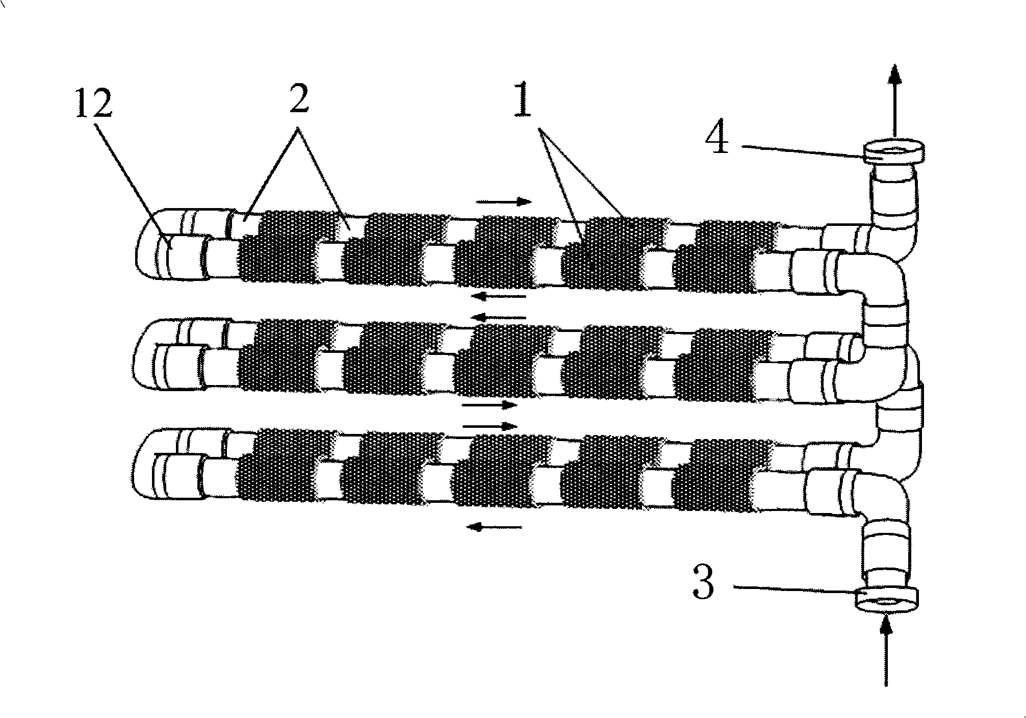
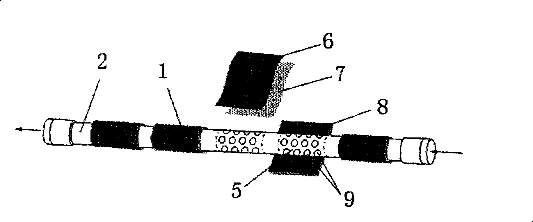
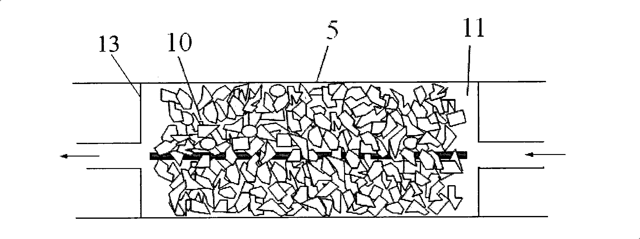
[0030] The invention provides a microbial fuel cell stack, which is a coil structure, as attached figure 1 , attached figure 2 And attached image 3 As shown, the microbial fuel cell stack is composed of several microbial fuel cell cells 1, the microbial fuel cell cells 1 include a hollow skeleton 5, a membrane cathode 8 and an anode 10, and the membrane cathode 8 wraps the hollow skeleton 5 An anode chamber 11 is formed, and the anode 10 is placed in the anode chamber 11; the cathode and the anode are respectively drawn out by wires; the plurality of microbial fuel cell cells 1 are connected end to end through the pipeline 2, and each anode chamber is connected to each other; the pipeline 2 A feed port 3 and a discharge port 4 are provided.

[0031] The skeleton 5 can be integrated with the pipe, that is, a section of hollow is sequentially taken as the skeleton on the pipe, and the distance between the skeletons can be 2-20 cm. The pipes are processed from cheap insulati...

Embodiment 2

[0037] This example illustrates the microbial fuel cell stack provided by the present invention and the method for treating brewery wastewater using the device.

[0038] (1) Construction of battery stack

[0039] as attached figure 1 Shown, be that the PVC pipe interval of pipe diameter 5cm gets section as skeleton 5, and skeleton 5 is long 13cm. Each PVC pipe is arranged with five single microbial fuel cells 1, and the anode chambers of the five single microbial fuel cells 1 are connected and connected end to end in turn through the connection of the pipes. The two PVC pipes are placed side by side to form a layer, and the attached figure 1 As shown in , the six PVC pipes are arranged in three layers, and the six PVC pipes are connected in turn through the elbow 12, and one end of the first and sixth pipes is respectively set as the feed port 3 and the discharge port 4 . In this way, a cell stack is composed of three layers of 30 individual microbial fuel cells, and each i...


PUM

PropertyMeasurementUnit
diameteraaaaaaaaaa
pore sizeaaaaaaaaaa
diameteraaaaaaaaaa

Abstract

The invention discloses a microbiological fuel cell stack, comprising a plurality of microbiological fuel cell singletons; the microbiological fuel cell singleton comprises a hollow framework, a film anode and an anode; the film cathode enwraps the hollow framework to form an anode chamber; the anode is arranged in the anode chamber; conductive wires are respectively guided out of the film cathode and the anode; a plurality of microbiological cell singletons are connected end to end by a pipeline; all anode chambers are communicated with each other; the cell stack is provided with a material inlet and a material outlet. The microbiological fuel cell stack of the invention overcomes the shortage that the structure and the running type of the existing microbiological fuel cell are not beneficial to the extension and amplification and the cost is high, and has the advantages of easy extension, uniform material feeding and material outgoing, compact structure, low manufacture cost, high output power compactness, and good COD removal effect, etc.

Description

technical field [0001] The invention belongs to the technical field of environment and new energy, and in particular relates to a microbial fuel cell stack. Background technique [0002] Energy shortage and organic waste disposal are two major challenges facing the world today. [0003] Microbial fuel cell (MFC) is a power generation device that directly converts chemical energy in organic matter into electrical energy, and has dual functions of power generation and waste disposal. MFC has a wide range of fuels. Domestic sewage, high-concentration organic wastewater, human and animal manure, etc. can be used as fuel for MFC. It can effectively remove organic matter while generating electricity. Therefore, it is an advanced biomass energy utilization technology with great development potential. It is expected to become a pillar technology for future organic waste treatment. [0004] The basic principle of MFC is: organic matter is oxidized by microorganisms in the anaerobic...

Claims


Application Information

Patent Timeline
Patent Type & Authority Applications(China)
IPC IPC(8): H01M8/16H01M8/24H01M8/2455H01M8/2483
CPCY02E60/527Y02E60/50Y02P70/50
Inventor 周顺桂
Owner GUANGDONG INST OF ECO ENVIRONMENT & SOIL SCI
Why Eureka
Try Eureka