
Tube fin brazing process and internal tube heating soldering machine for

A brazing process and brazing machine technology, applied in electric heating devices, manufacturing tools, metal processing and other directions, can solve the problems of difficult temperature control, poor brazing effect, etc., and achieve long service life, reasonable structure, and easy operation. Effect

Inactive Publication Date: 2008-12-10
AECC AERO SCI & TECH CO LTD
View PDF0 Cites 15 Cited by
  • Summary
  • Abstract
  • Description
  • Claims
  • Application Information

AI Technical Summary

Problems solved by technology

[0003] The present invention is made in order to solve the above problems, and its purpose is to provide a process method for heating brazing tube fins in a conduit or similar cavity and a tube heating brazing machine to solve the problems caused by traditional brazing heating methods. Since the conduit reaches the brazing temperature, the temperature is not easy to control, the brazing cannot completely penetrate to fill the joint gap, and the brazing effect is poor

Method used


Image

  • Tube fin brazing process and internal tube heating soldering machine for
  • Tube fin brazing process and internal tube heating soldering machine for
  • Tube fin brazing process and internal tube heating soldering machine for

Examples


Embodiment Construction

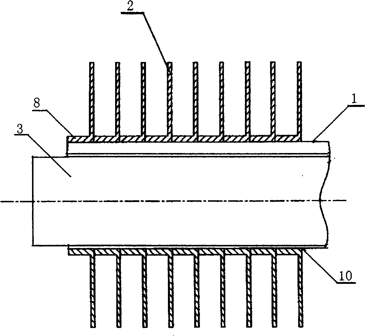
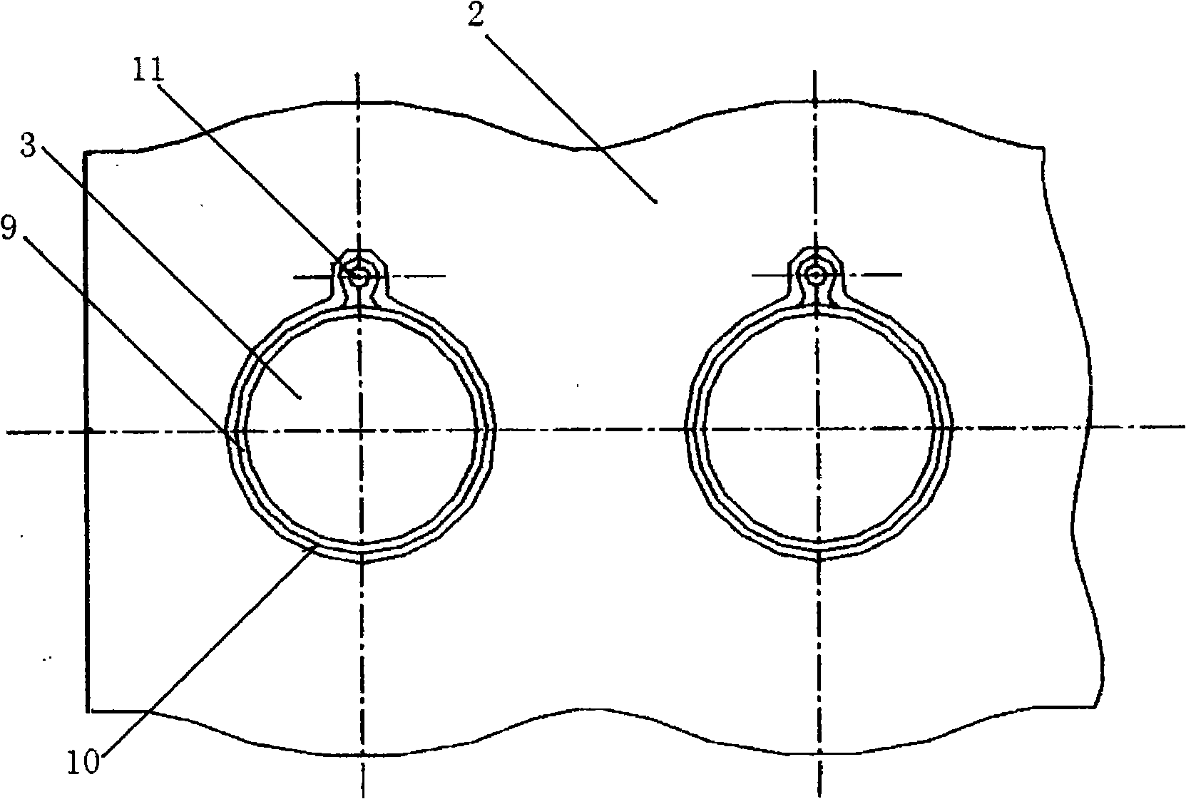
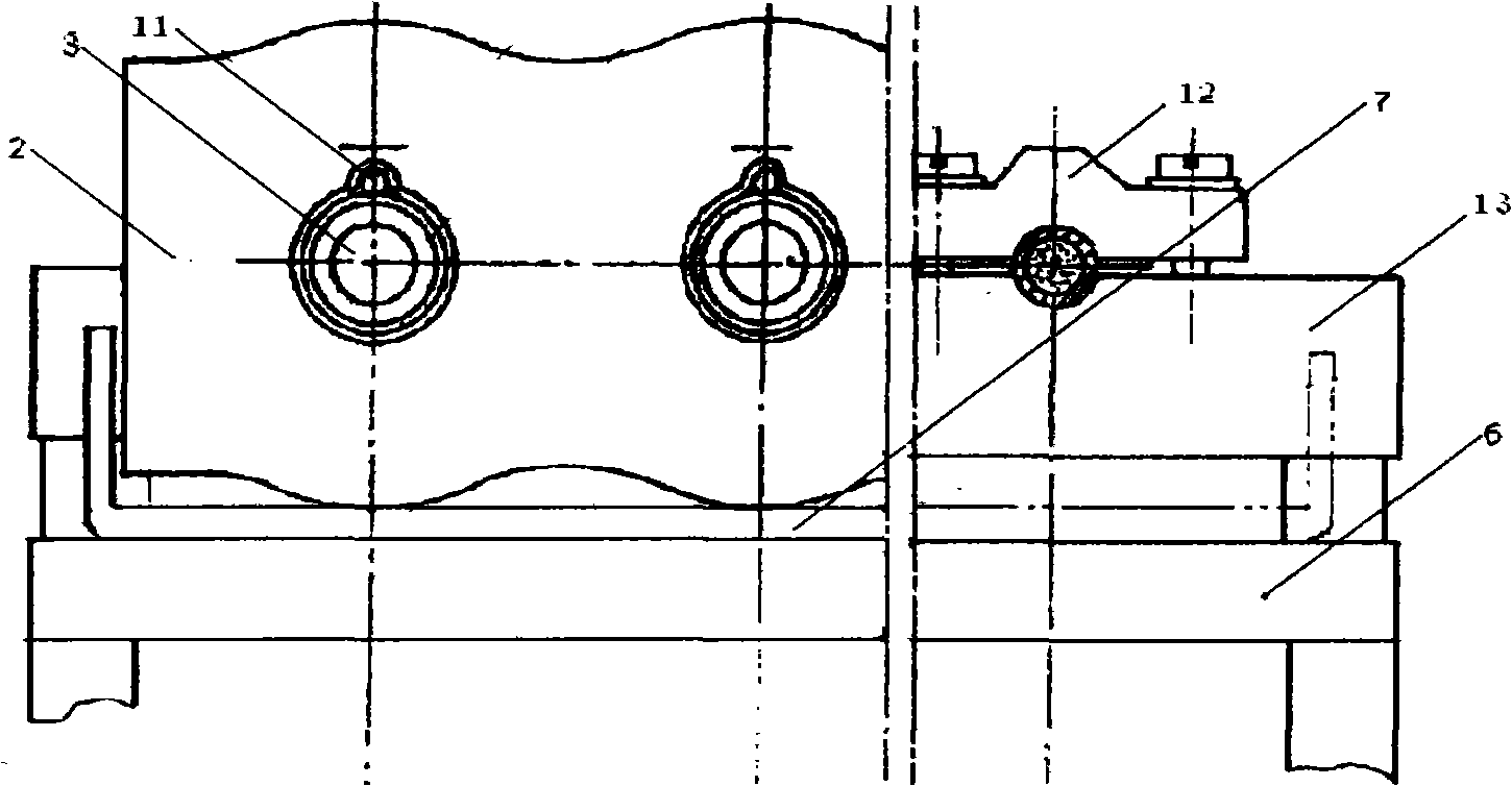
[0015] refer to Figure 1 ~ Figure 2 . The finned tube heat exchanger is composed of multiple pipes 1 and several pieces of fins 2 . The fins 2 are arranged parallel to each other, and are connected through at least two vertical ducts 1 . Each fin 2 is punched with a fin turning edge hole for assembling the conduit 1 on the same plane. And the top of the flanging hole is also punched with a notch 11 for placing solder. A single electric heating tube 3 passes through the catheter 1-shaped lumen. Before brazing, the pipe 1 workpiece equipped with fins 2 must be carefully processed and strictly cleaned to remove oil stains and excessively thick oxide films to ensure the assembly clearance of the fins' folded edge 8 interface. The gap is generally required to be between 0.01 and 0.1 mm. Fill the notch 11 of the joint gap with filling brazing solder with a melting point lower than that of the weldment, and place the finned tubular conduit weldment with the solder 9 assembled o...


PUM


Abstract

The invention discloses a tube fin brazing process and an in-tube heating brazing machine and is characterized in that a finned tubular pipe welding element well filled with solders is placed on a bracket and the surfaces of welding elements to be brazed are chemically cleaned; a rod type electric heating tube extends into the pipe to perform in-tube radiation heating to firstly moisten and apply the solders at the external wall of the pipe to fill the brazing gaps and then transfer the temperature to a finned folding edge by liquid solders; the metallurgical bonding is formed between the solders and the pipe as well as the folding edge by the atomic diffusion and solution. By adopting the in-tube heating brazing machine which consists of a machine stand, the bracket which is arranged at the front end of the machine stand and a heating tube holder arranged at the bracket, the tube fin brazing process and the in-tube heating brazing machine have the advantages of simple and convenient operation, minimal investment, no limitation to the geometric shapes of the brazed elements, no damage to the surfaces of the brazed elements and no change of the crystal structures in metals and solve the problems that the fins reach the brazing temperature before the pipes and the temperature is not easily controlled, and the brazing can not completely penetrate and fill the connection gaps and the brazing effect is bad, and the problems are caused by the traditional brazing heating ways.

Description

technical field [0001] The invention relates to a tube-fin brazing process and a tube-fin brazing machine. The tube-fin brazing process and the tube-fin heating brazing machine involved in the description of the invention are used for finned tube heat exchange The tube fins of the device are the brazing process method of the main object, but it can be considered that the tube fin brazing process and the inner heating brazing machine involved in the description of the present invention can also be applied to other structures with at least one or more The tubes pass through the brazing of a set of thin fins at the same time, such as fin heat exchangers used in refrigeration, HVAC, compressors, automobiles, oil cooling and other industries. Background technique [0002] In the prior art, the finned tube heat exchanger is provided with a plurality of fins arranged in parallel with each other separated by small gaps and a plurality of tubes vertically penetrating these fins and f...

Claims


Application Information

Patent Timeline
Patent Type & Authority Applications(China)
IPC IPC(8): B23K1/005B23K1/20B23K3/00B23K3/047B23K101/08
Inventor 刘建易学斌王福田
Owner AECC AERO SCI & TECH CO LTD
Learn More