Asymmetric structure three-dimensional co-vibrating spherical vector hydrophone

A vector hydrophone, an asymmetric technology, is applied to transducers used underwater, vibration measurement in fluids, instruments, etc. The hydrophone has high density, inconsistent sensitivity and phase characteristics, etc., to ensure that the acoustic characteristics do not change, reduce the number of internal sensors, and reduce the overall average density.

Inactive Publication Date: 2008-12-10
HARBIN ENG UNIV
View PDF0 Cites 11 Cited by
  • Summary
  • Abstract
  • Description
  • Claims
  • Application Information

AI Technical Summary

Problems solved by technology

Therefore, the three-dimensional co-vibration spherical vector hydrophone is usually designed with a symmetrical structure, that is, two vibration sensors are placed symmetrically on each of the three orthogonal channels, and six vibration sensors are evenly distributed on a spherical surface to ensure To meet the above conditions, the three-dimensional co-vibration spherical vector hydrophone with a symmetrical structure design needs six vibration sensors inside, and the phase consistency requirements for each pair of paired sensors are very strict, otherwise the phase inconsistency of the two paired sensors will cause The sensitivity and phase characteristics of this channel are inconsistent with those of other channels, mainly affecting the working frequency band and narrowing the working frequency band. This structure will not only make the design cost of the co-vibration vector hydrophone very high, but also have high quality and high density. Unstable

Method used


Image

  • Asymmetric structure three-dimensional co-vibrating spherical vector hydrophone
  • Asymmetric structure three-dimensional co-vibrating spherical vector hydrophone
  • Asymmetric structure three-dimensional co-vibrating spherical vector hydrophone

Examples


Embodiment Construction

[0020] The present invention is described in more detail below in conjunction with accompanying drawing example:

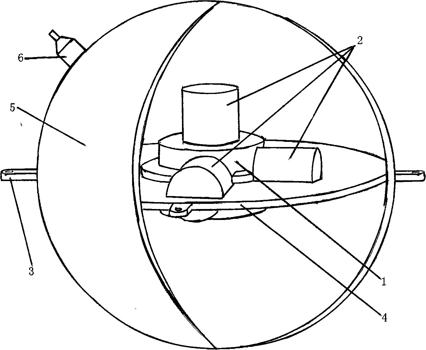
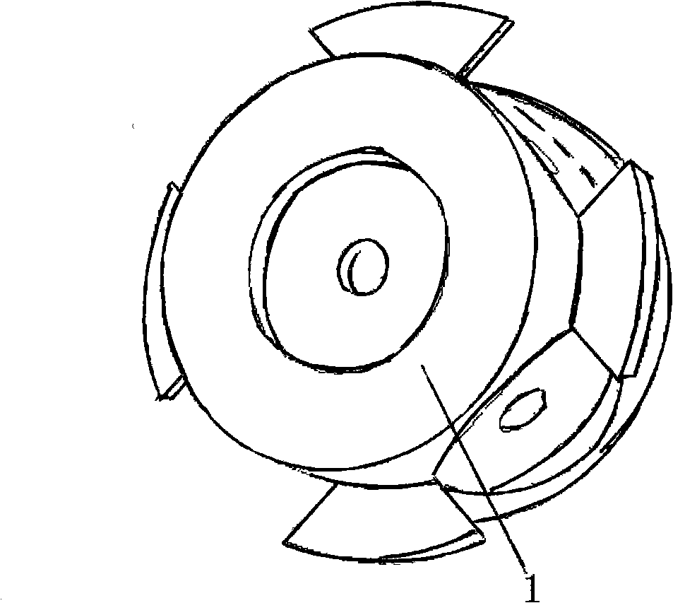
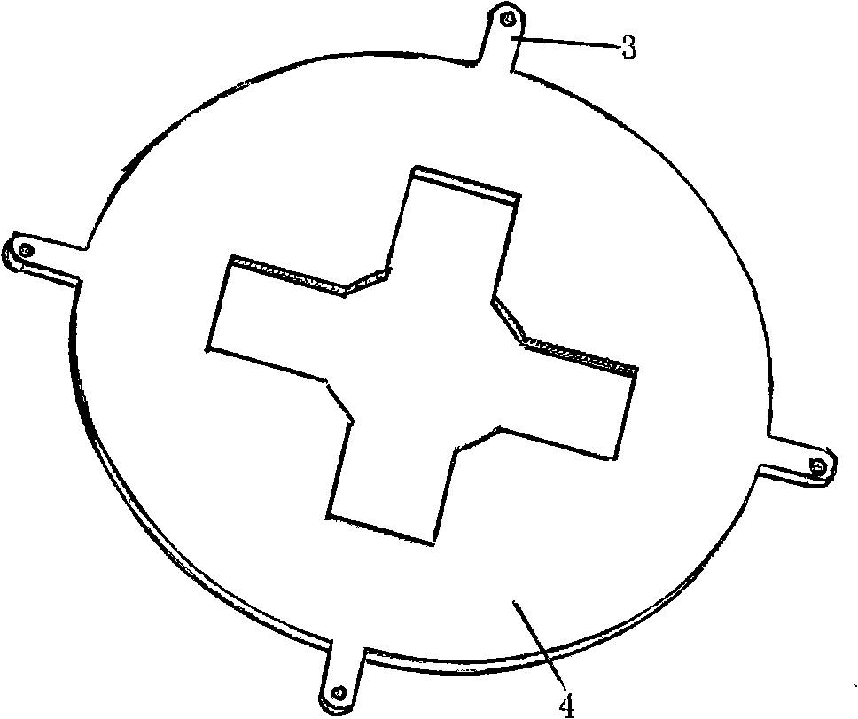
[0021] combine Figure 1 to Figure 3 , the asymmetric structure three-dimensional co-vibration spherical vector hydrophone of the present invention consists of a core vibrator composed of three piezoelectric accelerometers 2 installed on the center mass 1 and a support flange 4 with a suspension ring 3 and an upper and lower Two hemispherical shells 5 and an output cable 6 are formed. The core vibrator is fixed inside the support flange 4 by bolts, and the support flange 4 is sandwiched between the upper and lower hemispherical shells 5 by bolts and sealing rings.

[0022] First, three piezoelectric accelerometers 2 are axially installed on the central mass 1 to form a core vibrator, and then the core vibrator is fixed on the support flange 4 with a suspension ring 3 with bolts, and finally the support method The blue plate 4 is sandwiched between the upper and ...


PUM


Abstract

The invention provides a 3D co-vibration spherical vector hydrophone with an asymmetrical structure which includes an upper half spherical shell, a lower half spherical shell, an output cable and a core vibrator; the core vibrator consists of three piezoelectric accelerometers which are asymmetrically arranged on a central mass block; the core vibrator is arranged in a supporting flange; the supporting flange is clamped between the upper half spherical shell and the lower half spherical shell by a bolt and a seal ring. The quantities of the internal piezoelectric accelerometers needed by the hydrophone of the invention are less, the integral average density is low and the physical dimension is small; besides, the internal piezoelectric accelerometers have better cosine directivity and phase characteristics. Therefore, the low-frequency vector hydrophone not only has the advantages of small size, light weight and good directivity, but also has the advantages of good channel sensitivity and phase characteristics; the hydrophone can solve the design problem of a sonar array. The 3D co-vibration spherical vector hydrophone with the asymmetrical structure can be broadly applied into each field of underwater sound like a sonobuoy system, a low noise measuring system, a double-base sonar system, a torpedoe navigation system, an underwater communication system, a responder, and the like, to accomplish a lower frequency measuring task.

Description

(1) Technical field [0001] The invention relates to an underwater signal receiving device, in particular to a three-dimensional co-vibration spherical vector hydrophone. (2) Background technology [0002] The vector hydrophone is a new type of underwater receiving transducer, which can measure the sound pressure and particle vibration velocity, or sound pressure and particle acceleration, or sound pressure and sound Scalar and vector information in underwater sound fields such as pressure gradients. According to different working principles, vector hydrophones can be divided into two categories: differential pressure vector hydrophones and co-vibration vector hydrophones. At present, the co-vibration vector hydrophone is widely used in various fields of underwater acoustic engineering, especially in the low frequency band (below 1000Hz). [0003] "Applied Acoustics", 2001, 20(4): 15-20, in the article titled "Characteristics and Structural Design of Three-dimensional Co-vi...

Claims


Application Information

Patent Timeline
IPC IPC(8): G01H3/00G01H5/00H04R1/44
Inventor 陈洪娟张虎杨赟
Owner HARBIN ENG UNIV
Why Eureka
Try Eureka