Hot cathode fluorescent lamp filament current control circuit

A filament current and control circuit technology, applied to light sources, electric light sources, electrical components, etc., can solve the problems of shortening the life of lamp tubes, tungsten evaporation, and affecting the luminous efficiency of fluorescent lamps, achieving soft start and soft shutdown, Achieving Precisely Controlled Effects

Inactive Publication Date: 2008-12-10
TIANYU INFORMATION TECH SHANGHAI
View PDF0 Cites 2 Cited by
  • Summary
  • Abstract
  • Description
  • Claims
  • Application Information

AI Technical Summary

Problems solved by technology

A common simple fluorescent lamp filament heating circuit such as figure 2 As shown, the lamp drive power is connected to the fluorescent lamp from the input terminals A and B. During the preheating period of the circuit, the filament is preheated through the current between the filament and the starting capacitor. After the fluorescent lamp completes the ignition work, the filament current is composed of two parts, one part Part of the lamp current to make the lamp glow is the resonant capacitor current that controls the lamp voltage. At low brightness, the lamp current is very small, only a few milliamps, while the resonant capacitor current is very large, up to 0.6 amperes or more , causing the filament to be easily damaged at low brightness
like Figure 4 As shown, the lamp current will flow from one end to the other on the filament, which will generate a lot of heat on the filament, and make the filament temperature very high and difficult to control accurately
image 3 Shown is the filament heating circuit of a common hot cathode fluorescent lamp HCFL electronic ballast at present. The lamp tube driving power is connected to the fluorescent lamp from the input terminals A and B, and the filament is independently heated by the transformer coupled current. The effect of filament heating current and lamp current, such as Figure 4 As shown, in this circuit, the lamp current will flow from one end to the other end on the filament. The current passing through the filament includes the filament heating current and the lamp current. Since the lamp current will vary greatly during the dimming process, The current through the filament changes greatly, making the temperature of the filament very high and unstable, making it difficult to accurately control the temperature of the filament
The life of the cathode determines the life of the fluorescent lamp. If the cathode current is too large, the filament will overheat, which will accelerate the evaporation of the oxide material.
If the cathode current is too small and the cathode temperature is insufficient, the lamp life will also be shortened.
Since the thermal expansion coefficient of the tungsten filament that makes up the filament is inconsistent with the electron emission material on its surface, the instantaneous large filament current can accelerate the peeling off of the electron emission material, which affects the service life and luminous efficiency of the fluorescent lamp
[0003] Because HCFL lamps have negative resistance characteristics, that is, the lower the current, the higher the voltage. This characteristic of HCFL prevents them from working directly in parallel. Usually, to balance the current of parallel lamps, an external choke coil is used to change the lamp. tube impedance characteristics, increasing the cost

Method used


Image

  • Hot cathode fluorescent lamp filament current control circuit
  • Hot cathode fluorescent lamp filament current control circuit
  • Hot cathode fluorescent lamp filament current control circuit

Examples


Embodiment Construction

[0023] The present invention will be described in further detail below in conjunction with the accompanying drawings and specific embodiments.

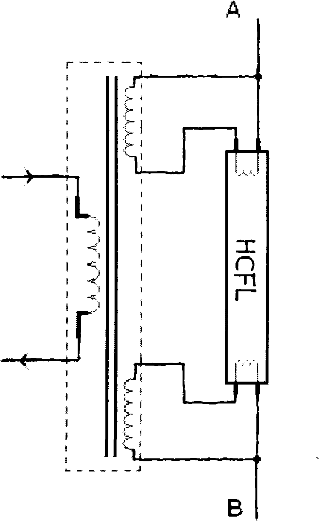
[0024] The hot cathode fluorescent lamp filament current control circuit of the present invention is as follows: Figure 7 and Figure 8 As shown, the circuit includes a filament heating transformer 1, the filament heating transformer 1 includes a primary coil and at least one secondary coil, and also includes a filament current control loop, the filament current control loop includes a power switch 2, a control logic 3, a multi-input comparator 4. Current control switch 5, oscillator OSC, reference voltage source VREF, reference current source IFER, primary coil current sampling resistor R0, filter capacitor C1, filter resistor R1 and other devices. The two ends of the secondary coil of the filament heating transformer 1 are respectively connected with the two ends of a hot cathode filament of the fluorescent lamp. It is connected ...


PUM


Abstract

The invention provides a filament current control circuit of hot-cathode fluorescent lamp, which is used for accurately controlling the filament current of hot-cathode fluorescent lamp, comprising a filament heating transformer and a filament current control loop. A primary loop of the filament heating transformer is connected with the filament current control loop, and two ends of secondary loop are respectively connected with two ends of a hot-cathode filament of fluorescent lamp. The driving power supply of the fluorescent lamp is connected to a centre tap of the corresponding secondary loop. The filament current control loop comprises a power switch, a control logic, a multiple-input comparator, an oscillator, a reference voltage source, a reference current source, a primary loop current sampling resistor, a filtering capacitor, a filtering resistor and so on. By using the filament current control circuit of hot-cathode fluorescent lamp in this invention, the influence of the lamp tube on the temperature of filament can be reduced, the filament current can be accurately controlled, the temperature of filament can be stabilized, the service life of fluorescent lamp can be prolonged, and the current balance of shunt-wound fluorescent lamp can be realized without using an extra choke coil.

Description

technical field [0001] The invention relates to a fluorescent tube drive technology, specifically to a fluorescent tube cathodic protection technology, in particular to a hot cathode fluorescent lamp filament current control circuit. Background technique [0002] As an energy-saving light source, the hot cathode fluorescent lamp HCFL has been widely used, such as figure 1 As shown, the hot cathode of HCFL is located at both ends of the fluorescent tube. The hot cathode is made of a helical tungsten wire wound into a spiral shape. Its surface is covered with materials that can emit electrons. When the temperature of the filament is constant, at both ends of the filament When a certain voltage is applied, the filament can emit thermal electrons, which excite mercury vapor to collide with phosphor to emit light. Such as Figure 4 As shown, according to the structure of the cathode, using the characteristics of the electromagnetic field to analyze, it can be known that the ele...

Claims


Application Information

Patent Timeline
Patent Type & Authority Applications(China)
IPC IPC(8): H05B41/295H05B41/36
Inventor 陈忠志柯宇张良
Owner TIANYU INFORMATION TECH SHANGHAI
Why Eureka
Try Eureka