
Immersed inflating and stirring device of injection type floatation cell for coal separation

A technology of inflatable stirring and flotation machines, applied in the field of flotation machines, which can solve the problems of increased wear, energy loss, and short service time, and achieve the effect of reliable operation and long service life

Active Publication Date: 2008-12-17
BEIJING GUOHUA TECH GRP LTD
View PDF0 Cites 9 Cited by
  • Summary
  • Abstract
  • Description
  • Claims
  • Application Information

AI Technical Summary

Problems solved by technology

[0004] 1. The service life of the throat and umbrella diffuser is short
Due to the large size of these two parts, they are generally made of gray cast iron, especially in coal preparation plants equipped with dense medium separation technology, due to the influence of the clean coal magnetic separator process effect, the flotation feed will be carried to varying degrees Magnetite powder, thus aggravating wear and tear, so the above two use time is short, and some coal preparation plants even only have more than half a year
[0005] 2. The lower end of the throat in the inflatable stirring device of the current flotation machine is equipped with an umbrella-shaped disperser. After being stirred, the circulating coal slurry is obliquely ejected from the six channels of the umbrella-shaped disperser, which will lose part of the energy and reduce the injection speed.
[0006] 3. The central feeding pipe and the upper end of the throat of the existing flotation machine protrude from the coal slurry liquid level, and many mechanical parts hinder the swimming of the foam layer, which affects the working effect

Method used


Image

  • Immersed inflating and stirring device of injection type floatation cell for coal separation
  • Immersed inflating and stirring device of injection type floatation cell for coal separation

Examples


Embodiment Construction

[0021] The present invention will be further introduced below in conjunction with the accompanying drawings and embodiments.

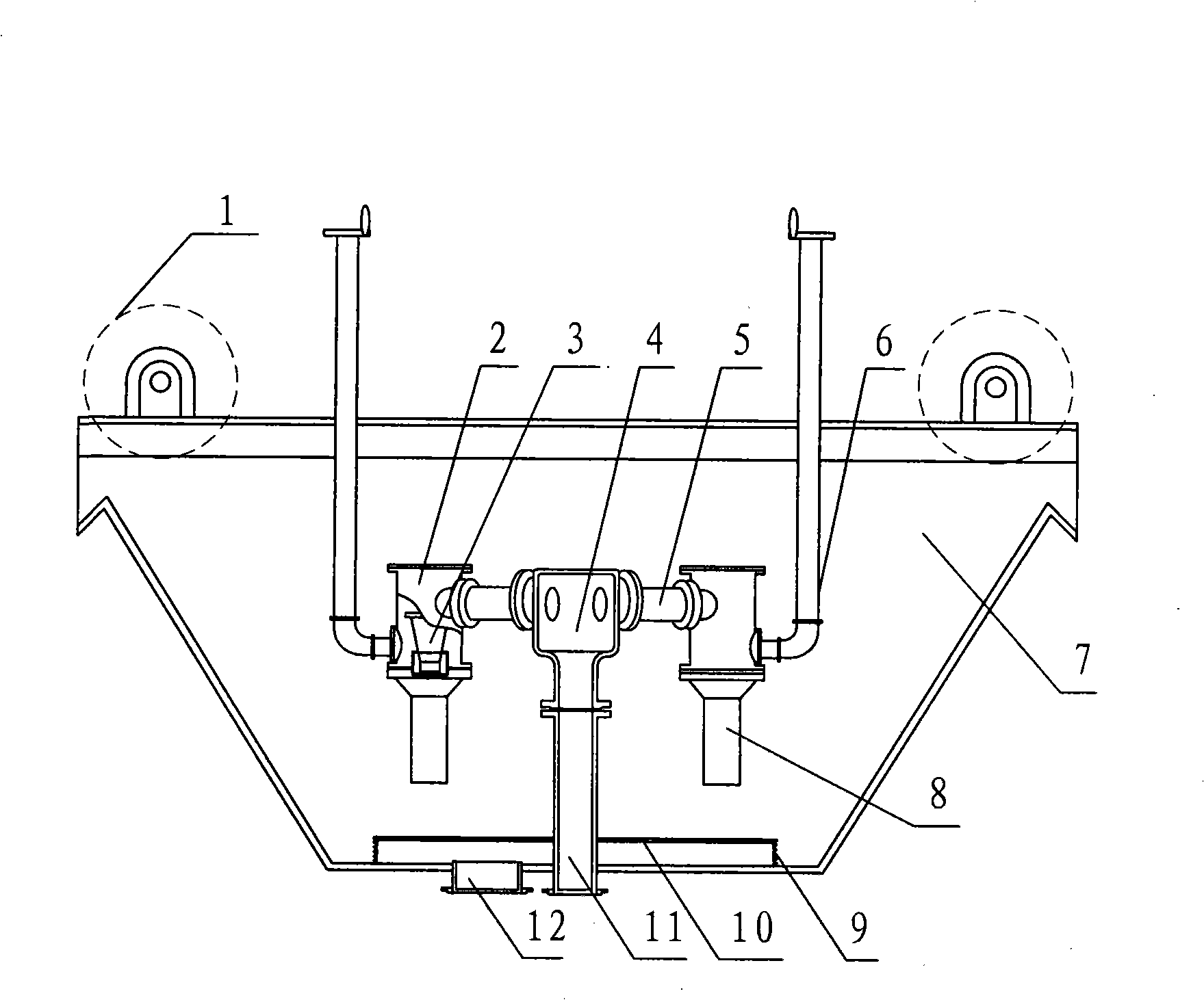
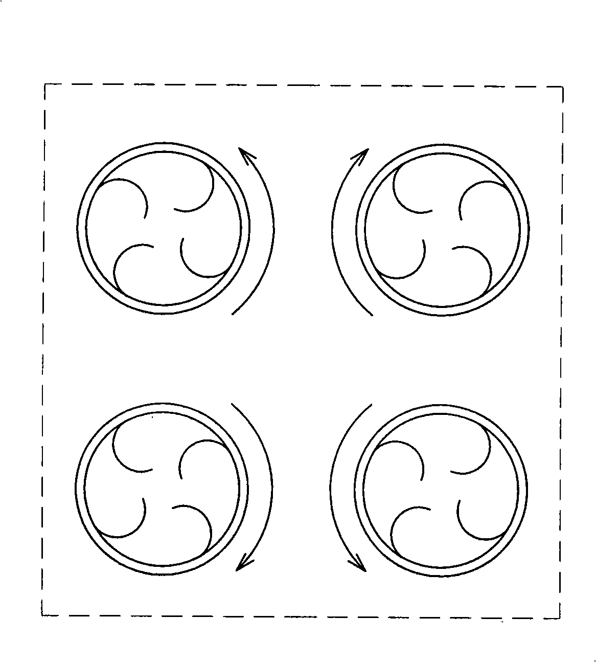
[0022] See attached Figure 1~2 , In this embodiment, the aeration stirring device is placed inside the flotation machine tank 7, and the device is composed of a spray chamber 2, a nozzle 3, a short throat 8 and a suction pipe 6 and the like. Wherein, the lower end of the distribution chamber 4 located in the center of the flotation machine tank is fastened with the upper end of the central feeding pipe 11, and the two are internally connected, and the lower end of the central feeding pipe 11 protrudes from the bottom of the tank body 7 The outer wall of the distribution chamber 4 is evenly equipped with four spray chambers 2 arranged in a radial pattern. The distribution chamber 4 communicates with each spray chamber 2 with a connecting short pipe 5. Connected with guide vanes, wherein the direction of rotation of the nozzle guide vanes in the two in...


PUM


Abstract

The invention relates to a floatation machine applied to the coal dressing process, in particular to an immersion-typed aeration agitation device for jet flotation machine for coal dressing. The immersion-typed aeration agitation device comprises jet chambers, nozzles, hollow throats and air suction pipes. Arranged at the central part of a groove body of the floatation machine, connection pipes for distribution chamber are radially communicated with four jet chambers and the nozzles arranged in the jet chambers are fixedly connected with guide vanes; the external side of the jet chamber is communicated with the air suction pipe and the lower end of the jet chamber is connected with the hollow throat; the turning directions of the guide vanes of the nozzle arranged in the jet chamber at the same side of the axis of the distribution chamber are opposite; the hollow throat is a short one, the other end of which is suspended in the air; a wear-resistant liner is fixed connected with the internal wall of the short hollow throat; the upper end of the air suction pipe of the aeration agitation device extends from the liquid surface of coal paste and the remaining parts of the aeration agitation device are all immersed in the coal paste. The circulating coal paste is fed following tangent lines of different directions and a hydraulic stirring is carried out in each jet chamber to improve the aeration agitation effect. The immersion-typed aeration agitation device works reliably, has long service life, consumes less power and requires low maintenance cost.

Description

technical field [0001] The invention relates to a flotation machine used in a coal preparation plant, in particular to a submerged air-filled stirring device of a jet flotation machine for coal preparation. Background technique [0002] In each flotation cell of the existing FJC series jet flotation machine for coal, four inflatable stirring devices are radially arranged. tube composition. The upper end of the injection chamber and the throat is above the flotation liquid level. The circulating coal slurry is pressurized by the circulation pump and enters the nozzle in the injection chamber. Guide vanes are cast in the nozzle, and the jet stream is ejected at high speed from the nozzle outlet in a spiral expanding shape. , A suction phenomenon occurs in the spray chamber, so the air is inhaled through the suction pipe and wrapped into the jet flow, and then obliquely shoots to the false bottom of the flotation machine through the throat pipe and umbrella-shaped disperser, s...

Claims


Application Information

Patent Timeline
IPC IPC(8): B03D1/02B03D1/14
CPCB03D1/242
Inventor 吴大为江明东王微微
Owner BEIJING GUOHUA TECH GRP LTD
Learn More