

Intelligent printing mechanism for large infusion soft bag production line
A printing mechanism and production line technology, applied to typewriters, printing, printing devices, etc., can solve the problems of high printing cost, high energy consumption, and low thermal efficiency, so as to improve production efficiency and product quality, improve printing speed and efficiency, and reduce The effect of cost of use
- Summary
- Abstract
- Description
- Claims
- Application Information
AI Technical Summary
Problems solved by technology
Method used
Image


Examples
Embodiment 1
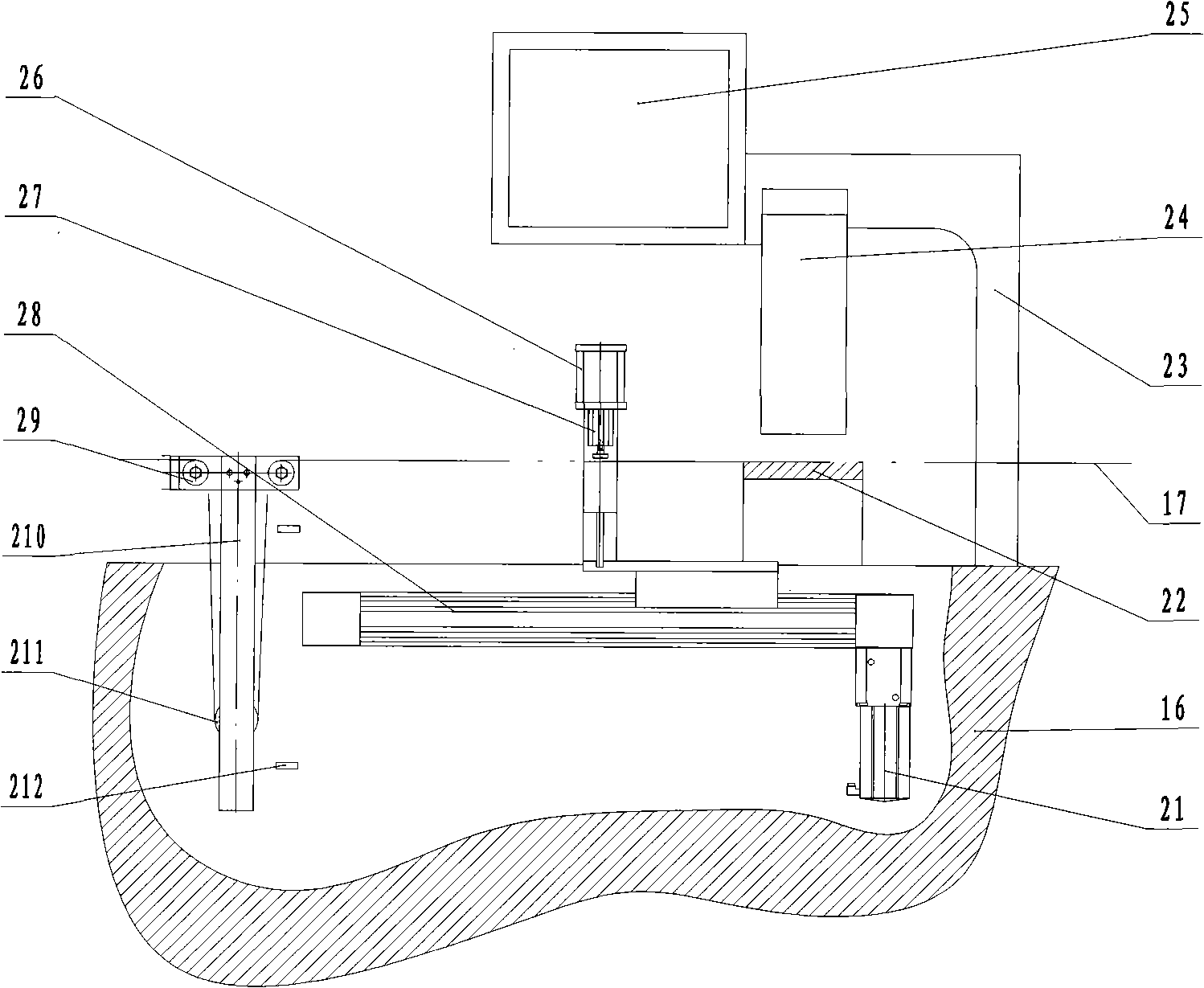
[0052] Embodiment 1: as figure 1 As shown, the intelligent inkjet coding system is directly applied to the large infusion soft belt production line without additional film delivery devices and film storage devices. The intelligent inkjet coding system includes a control panel 25, a chassis and at least one print head 24 (a print head is shown in the figure), and the chassis can be independent from the large infusion soft belt production line, or can be installed in the production frame 16, according to the manufacturer's production space depends. The print head 24 is installed on the printing frame 23, and its position is adjustable up, down, left, and right, and the best position of the best print head 24 is adjusted according to the inkjet code effect. The control panel 25 is fixed on the printing frame 23, and its direction and position are as the criterion for convenient operation and adjustment. The bag-making film 17 is sent to the printing head 24 through the film-fe...
Embodiment 2
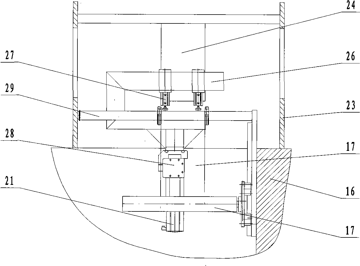
[0053] Embodiment 2: as figure 2 and image 3 As shown, the intelligent inkjet coding system is fixed on the printing frame 23, wherein the width direction of the print head 24 is the same as the width direction of the bag-making film 17. The film delivery system is installed on the frame 16, wherein the film delivery device is installed in front of the print head 24 (with reference to the moving direction of the bag-making film), and the film storage device is installed in front of the film delivery device. figure 2 shown. The film feeding device includes a film pulling frame 26, a film pressing cylinder 27, an electric motor 21 and a linear driver 28, the film pulling frame 26 is fixed on the linear driver 28, the electric motor 21 is connected with the linear driver 28, and the film pressing cylinder 27 is installed on the film pulling machine. On frame 26 and be positioned at the top of bag-making film 17. When starting to work, the film-drawing frame 26 of the film-f...
Embodiment 3
[0054] Embodiment 3: as Figure 4 and Figure 5 As shown, the intelligent inkjet coding system is fixed on the printing frame 23, wherein the width direction of the print head 24 is the same as the width direction of the bag-making film 17. The film feeding device is installed in front of the print head 24 (with reference to the moving direction of the bag-making film), and the film storage device is installed in the front of the film feeding device such as Figure 4 shown. The film feeding device includes an electric motor 21, an active film feeding roller 31, a driven film feeding roller 32, a pressure regulator 33 and a transmission system 34. The active film feeding roller 31 and the driven film feeding roller 32 are arranged oppositely and turn in opposite directions. The output end of 21 is connected with the active film feeding roller 31, and the active film feeding roller 31 is connected with the driven film sending roller 32 through the transmission system 34. The ...
PUM
 Abstract
Description
Claims
Application Information