Silo bottom rectifying energy dissipator

An energy dissipator and shaft technology, which is applied in waterway systems, climate change adaptation, sewage removal, etc., can solve the problems of difficulty in ensuring ventilation effects, large fluctuations in the surface of the water flow, and high impact pressure on the bottom plate, saving ventilation facilities and having a simple structure. , the effect of smooth flow transition

Inactive Publication Date: 2008-12-17
SICHUAN UNIV
View PDF0 Cites 13 Cited by
  • Summary
  • Abstract
  • Description
  • Claims
  • Application Information

AI Technical Summary

Problems solved by technology

For example, the depth of the stilling well set by the simple energy dissipator is small, and the impact pressure on the bottom plate is very high; the length of the pressure slope section of the curved and L-shaped energy dissipator i...

Method used


Image

  • Silo bottom rectifying energy dissipator
  • Silo bottom rectifying energy dissipator
  • Silo bottom rectifying energy dissipator

Examples


Embodiment 1

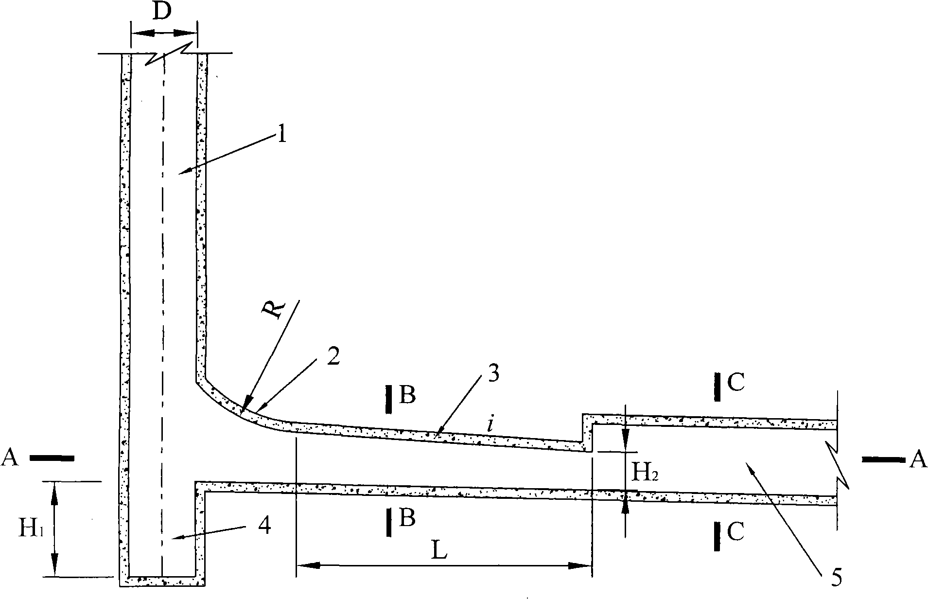
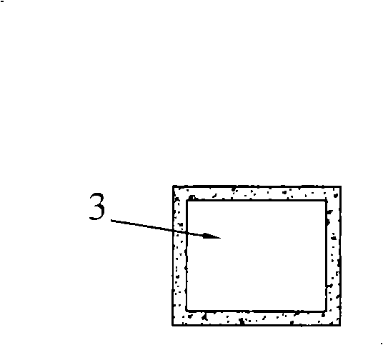
[0028] In this example, the maximum dam height of the hydropower station is 171m, the drop of vertical shaft 1 is 135m, and the flow rate of the flood discharge tunnel is 308.63m 3 / s, the diameter D of shaft 1 is 7m, and the cross section of spillway tunnel 5 is as follows Figure 4 As shown, its width is 5m, and the height of the straight wall is H 3 It is 7m.

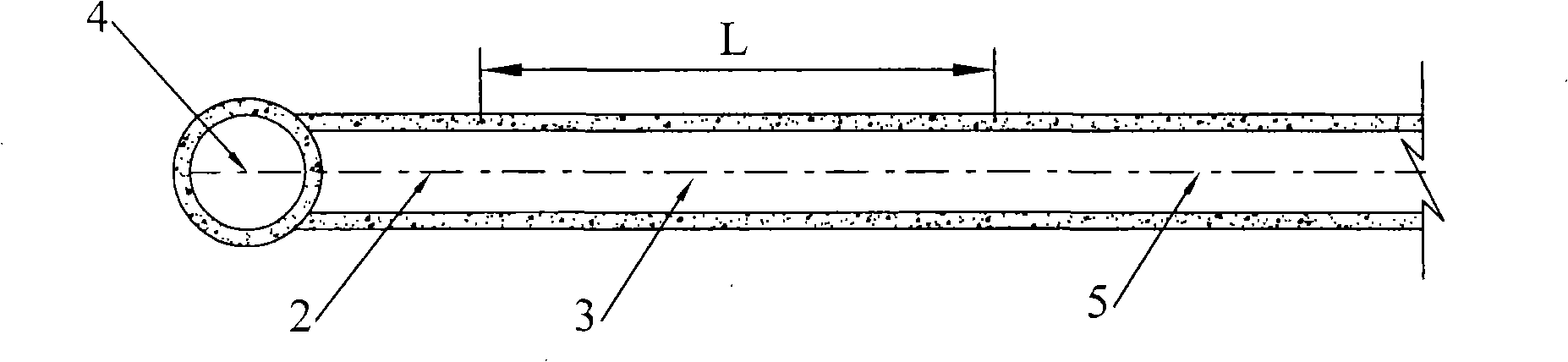
[0029] The structure of rectification energy dissipator at the bottom of the shaft is as follows: figure 1 , figure 2 As shown, it is composed of stilling well 4, anti-arc slope pressure section 2 and straight slope pressure section 3, and each part is made of concrete. The stilling shaft 4 is coaxial with the vertical shaft 1 and is located under the bottom of the flood discharge tunnel. The diameter of the stilling shaft is the same as that of the vertical shaft, which is 7m. The depth of the stilling shaft is H 1 is 10m. The anti-arc slope pressure section 2 and the straight slope pressure section 3 are an i...

Embodiment 2

[0032] In this embodiment, the maximum dam height of the hydropower station is 171m, the drop of shaft 1 is 135m, and the discharge volume is 308.63m 3 / s, the diameter D of the shaft 1 is 7m, the cross section of the flood discharge tunnel 5 is shown in Figure 9, its width is 5m, and the height of the straight wall is H 3 It is 7m.

[0033] The structure of the rectification and energy dissipation work at the bottom of the shaft is shown in Figure 6, Figure 7, and Figure 8, which is composed of a stilling shaft 4, an anti-arc slope pressure section 2 and a straight slope pressure section 3. The difference from Example 1 is: 1. The reverse-arc slope section 2 and the straight slope section 3 are manufactured separately. During installation, the inlet of the reverse-arc slope section 2 is connected to the shaft 1, and the outlet is connected to the straight-line slope section. The inlet end of 3 and the outlet end of the straight slope section 3 are connected to the flood disc...


PUM


Abstract

The invention provides a vertical shaft bottom rectifier dissipater, being composed of a baffle well, an ogee slope section and a linear slope section with rectangular ring-shaped cross-section; the baffle well and the vertical shaft have the same axial line and are arranged below the bottom surface of a spillway tunnel, with the depth of 1D-2D (D is the diameter of the vertical shaft); the water inlet end of the ogee slope section is connected with the vertical well and the water outlet end thereof is connected with the water inlet end of the linear slope section; the water outlet end of the linear slope section is connected with the spillway tunnel; the ogee slope section and the linear slope section can be respectively fabricated and connected during the installation process or fabricated into a whole. The rectifier dissipater has sufficient dissipation, is beneficial to the stable jointing of the vertical shaft water flow and the spillway tunnel water flow, improves the water flow state inside the spillway tunnel and ensures the safe running of the spillway tunnel.

Description

technical field [0001] The invention belongs to energy dissipation facilities in water conservancy and hydropower projects, in particular to an energy dissipation and flow state control device used at the bottom of a shaft flood discharge tunnel. Background technique [0002] Compared with the traditional shaft spillway, the swirling shaft is a new type of energy dissipator. In the swirling shaft, since the water flow rotates around the axis of the shaft and flows close to the wall, a stable cavity is formed in the center of the shaft, so it can not only maintain the stability of the water flow, but also form a good ventilation condition, avoiding the instability of the air bag appear. However, when the water flow in the vertical shaft rotates and enters the downstream, the flow velocity is very high. If a flood discharge tunnel is installed downstream, the connection between the vertical shaft and the downstream flood discharge tunnel is a difficult problem. [0003] The ...

Claims


Application Information

Patent Timeline
IPC IPC(8): E03F1/00E03F5/04E02B11/00
CPCY02A30/60
Inventor 刘善均许唯临张建民王韦邓军曲景学李贵吉王曾恩陈剑刚任雨
Owner SICHUAN UNIV
Why Eureka
Try Eureka