
Self-adapting closed-loop control flight light path mechanism and control method thereof

A flying optical path and closed-loop control technology, which is applied in the direction of feedback control, optics, manufacturing tools, etc., can solve problems such as complex control units, affecting the quality of beam transmission, and poor performance of adaptive components

Inactive Publication Date: 2008-12-17
CHONGQING UNIV
View PDF0 Cites 5 Cited by
  • Summary
  • Abstract
  • Description
  • Claims
  • Application Information

AI Technical Summary

Problems solved by technology

The disadvantages are: the deformable mirror requires a complex control unit, and the performance of the adaptive component is poor, such as the low precision and response characteristics of the component, which often affects the transmission quality of the beam

Method used


Image

  • Self-adapting closed-loop control flight light path mechanism and control method thereof
  • Self-adapting closed-loop control flight light path mechanism and control method thereof
  • Self-adapting closed-loop control flight light path mechanism and control method thereof

Examples


Embodiment Construction

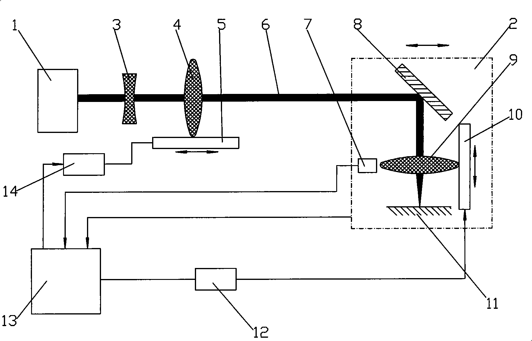
[0022] figure 1 It is a structural schematic diagram of the present invention, as shown in the figure: the flying optical path mechanism of the self-adaptive closed-loop control of the present embodiment includes a laser 1, a flying optical path and a drive control system, the flying optical path includes a flying focusing head 2 and a telescope system, and the flying focusing head 2 can reciprocate along the optical axis, the telescope system includes the eyepiece 3 and the objective lens 4, the flying focusing head 2 includes a plane mirror 8 and a focusing mirror 9, the plane mirror 8 is set at an angle of 45° relative to the optical axis, and the gap between the incident light and the reflected light The angle is 90°, which makes the structure of the mechanism compact and easy to control; the laser 1 and the eyepiece 3 are relatively fixed, and the light beam 6 emitted by the laser 1 passes through the eyepiece 3 and the objective lens 4 in turn, and is reflected by the pla...


PUM


Abstract

The invention discloses a self-adaptive closed-loop control flying optical path mechanism and a control method thereof. The flying optical path mechanism comprises a laser, a flying optical path and a drive control system; the flying optical path comprises a flying focusing head and a binocular system; the binocular system comprises an eyepiece and an object lens; the flying focusing head comprises a plane mirror and a focusing mirror; the laser and the eyepiece are relatively fixedly arranged; light beams which are emitted by the laser are reflected to the focusing mirror for focusing by sequentially passing through the eyepiece and the object lens; and the drive control system can drive the object lens and the focusing mirror to carry out the reciprocating motion along an optical axial line according to the position signals of the flying focusing head and the focusing mirror. The flying optical path mechanism has high-performance self-adaptability, and can improve the focusing feature of the flying light beams, accurately and reliably compensate the change of the depth of focus of a laser focus point and obtain the set focus size and the depth of the focus through controlling the positions of the beam expanding object lens and the focusing mirror along with the change of the flying distance; furthermore, the method is simple and reliable, a complicated control unit of a deformable mirror is eliminated, the structure is simple, and the cost is low.

Description

technical field [0001] The invention relates to a flying optical path mechanism and a control method thereof in the field of laser application technology, in particular to an adaptive closed-loop control flying optical path mechanism and a control method thereof. Background technique [0002] In the field of laser applications, such as large-scale laser processing, laser shooting, laser-driven aircraft and other fields, flying optics technology has been widely used due to its greater flexibility and portability. For example, in large-scale laser processing, since the large workpiece is long and heavy, if it moves longitudinally with the spindle during processing, it is prone to crawling and inaccurate positioning. Therefore, for the processing of large workpieces, the form of flying optics is usually used. [0003] The focusing characteristics of the flying beam mainly include the difference between the actual focal length and the geometric focal length (ideal geometric par...

Claims


Application Information

Patent Timeline
IPC IPC(8): G02B26/08G02B26/00G02B7/02G02B17/08B23K26/00G05D3/12B23K26/046B23K26/064
Inventor 万大平陈兵奎邵毅敏孟凡明
Owner CHONGQING UNIV
Learn More