Printer ink supply system

A printer and ink supply technology, which is applied in printing and other fields, can solve the problems of frequent switching of ink supply pumps, shortened service life, reduced work efficiency and cost, etc., and achieves the effects of easy recycling, reduced printing costs, and reduced ink waste

Active Publication Date: 2008-12-24
驱动数码电子(广东)有限公司
View PDF0 Cites 6 Cited by
  • Summary
  • Abstract
  • Description
  • Claims
  • Application Information

AI Technical Summary

Problems solved by technology

[0003] Based on the above control principle, the electromagnetic switch often has wrong control during the use process. For example, the ink supply pump is not activated when the ink is insufficient, resulting in a shortage of ink in the nozzle, or continuing to pump ink when the ink is sufficient, resulting in overflow. ink
On the one hand, this is caused by the control accuracy of the electromagnetic switch. The existing electromagnetic switch generally has an error of 5 to 15mm. When used in a machine such as a printer that requires precise control, the accuracy is obviously insufficient.
On the other hand, during the workin

Method used


Image

  • Printer ink supply system
  • Printer ink supply system
  • Printer ink supply system

Examples


Embodiment 1

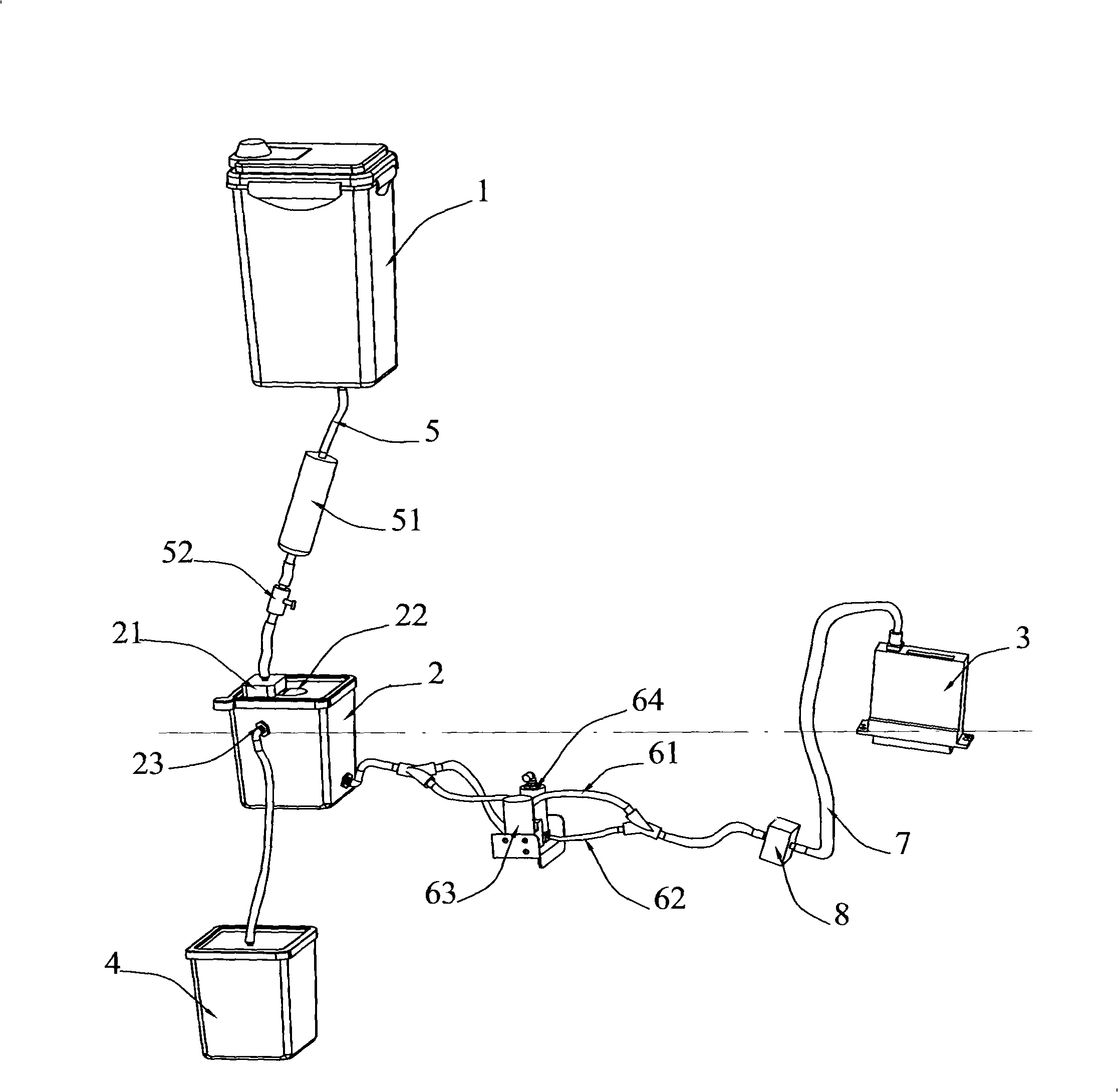
[0019] Such as figure 1 The schematic structural diagram of the ink supply system of the printer shown is mainly composed of the main ink tank 1, the auxiliary ink tank 2, the overflow bottle 4, the nozzle 3 and the ink transmission link between them. In terms of the installation position of the printer, the main ink tank 1 is installed at a position higher than the sub-ink tank 2, and is connected through the ink tube 5. The top of the sub-ink tank 2 is provided with a vent hole 22 to connect with the outside world, and the ink is automatically transferred from the main ink tank 1 through the hydraulic pressure difference. Pump to sub-cartridge 2. In order to ensure the quality of the ink and adjust the flow rate of the ink, a filter 51 and a valve 52 are respectively provided on the ink tube.

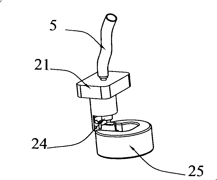
[0020] A float valve switch 21 is provided at the position where the lower end of the ink tube 5 is connected to the sub-ink box 2 to control the ink feeding of the ink tube 5, so as...

Embodiment 2

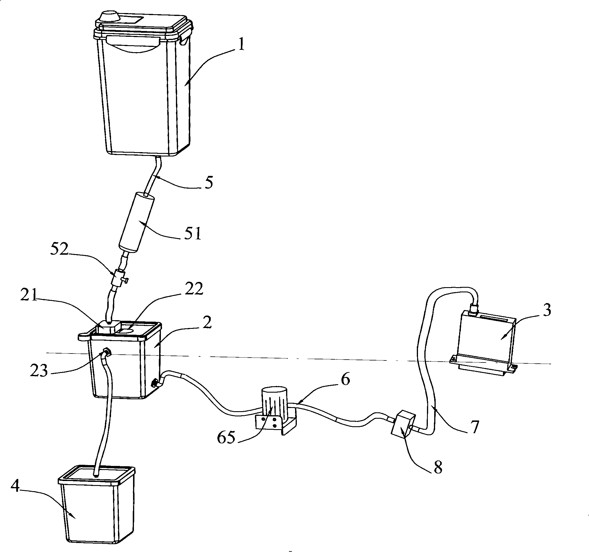
[0025] The present invention also has another embodiment on the basis of the above, as figure 2 Schematic diagram of the ink supply system of the printer shown. The difference from the previous embodiment is that the cleaning pump adopts a centrifugal pump 65, and its pipeline design is completely changed. Since the centrifugal pump 65 is connected internally when it is not working, only one ink supply pipe 65 is needed. Two functions of printing and cleaning can be realized. In the printing state, the centrifugal pump 65 is in a non-working state, and the ink flows from the sub-ink box 2 to the nozzle according to the printing requirements of the nozzle 3 . In the cleaning state, the centrifugal pump 65 is started, and the ink is sucked out from the sub-ink box 2 by centrifugal action, and sprayed out from the nozzle 3 to realize the cleaning of the nozzle 3 .


PUM


Abstract

The invention relates to the ink supplying system field of a printer. The technical problem to be solved is to overcome the defects of the prior art to provide a printer ink supplying system which can accurately supply ink to an auxiliary ink box from a main ink box and save ink. The printer ink supplying system mainly comprises the main ink box, the auxiliary ink box, an overflow pot and a nozzle. The installation position of the main ink box on the printer is higher than the auxiliary ink box. The main ink box is connected with the auxiliary ink box through an ink pipe and a float valve switch. The upper part of the auxiliary ink box is provided with an air vent, and the bottom is connected with the nozzle through an ink feeding pipe. The lateral of the auxiliary ink box is provided with an overflow port which is connected with an overflow bottle. The height of the overflow port is leveled with the liquid line of the nozzle. The ink feeding pipe is provided with a cleaning pump. In principle, the transportation of the ink is realized through the function of weight and is automatically controlled by the float valve switch. The sensing-acting process of the prior art is designed in the mechanism. The buoyancy natural control process is adopted. And the printer ink supplying system has the advantages of simple structure and accurate control.

Description

technical field [0001] The invention relates to the field of ink supply systems for printers, and more specifically relates to a printer ink supply system suitable for large printers, capable of accurately realizing ink supply control and saving ink. Background technique [0002] Existing printers, especially large-scale printers, generally have two sets of ink cartridges, ie, main ink cartridges and auxiliary ink cartridges, due to the large demand for ink. The main ink tank has a large capacity and heavy weight, and is generally installed on the printer body; the auxiliary ink tank has a general capacity and light weight, and can be installed on the printing jet truck to move with the printing jet truck. The main ink box, the sub-ink box and the nozzle are connected through the ink pipe in turn, and an ink supply pump is arranged between the main ink box and the sub-ink box. When the ink in the sub-ink box decreases, the ink supply pump can automatically replace the ink in...

Claims


Application Information

Patent Timeline
IPC IPC(8): B41J2/175
Inventor 汤振华
Owner 驱动数码电子(广东)有限公司
Why Eureka
Try Eureka