Method for detecting cutting fluid concentration during use

A detection method and technology of cutting fluid, applied in the field of detection of cutting fluid concentration in use, can solve problems such as inability to accurately measure the effective concentration of cutting fluid

Active Publication Date: 2008-12-24
CHINA PETROLEUM & CHEM CORP
View PDF0 Cites 9 Cited by
  • Summary
  • Abstract
  • Description
  • Claims
  • Application Information

AI Technical Summary

Problems solved by technology

[0009] The technical problem to be solved by the present invention is the problem that the existing technology cannot accurately measure the effective concentration of the dirty cutting fluid in use, and a new detection method for the concentration of the cutting fluid in use is provided

Method used


Image

  • Method for detecting cutting fluid concentration during use
  • Method for detecting cutting fluid concentration during use
  • Method for detecting cutting fluid concentration during use

Examples


Embodiment 1~8

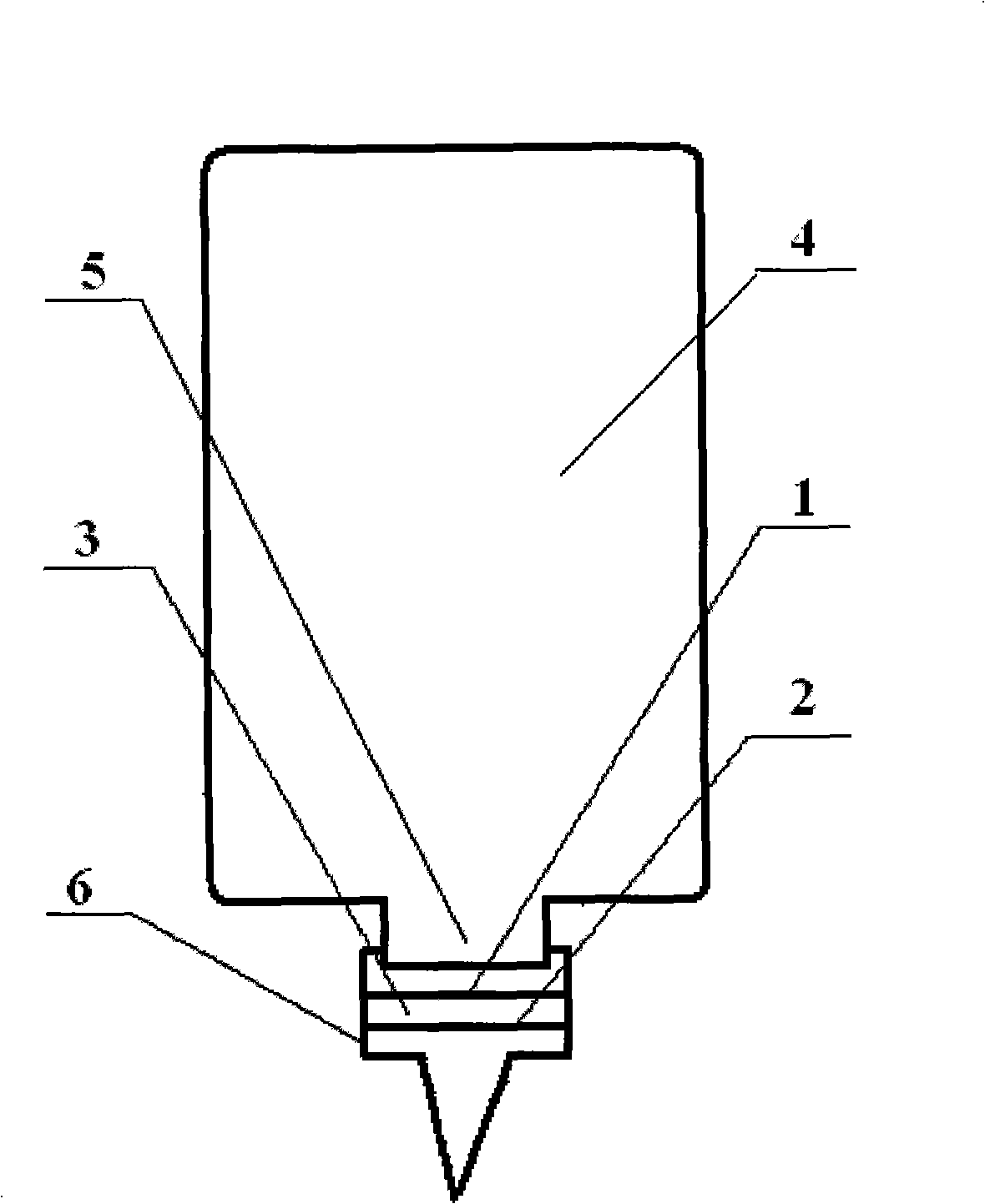
[0029] Add cutting fluid of known concentration to figure 1 In the sample preconditioner shown, then measure its refractive index with a refractometer, so as to convert the cutting fluid concentration. The conditions of each layer of filter membrane and adsorbent in the sample outlet of the preprocessor are shown in Table 1, and the test results are shown in Table 2.

[0030] Table 1 Filter membrane structure of preconditioner

[0031] Example

first filter membrane

Adsorbent

second filter membrane

third filter membrane

The fourth filter membrane

1

Qualitative filter paper

-

3 micron microporous membrane

-

-

2

Quantitative filter paper

charcoal

5 micron microporous membrane

-

-

3

Qualitative filter paper

-

8 micron microporous membrane

3 micron microporous membrane

-

4

Qualitative filter paper

-

1.2 micron microporous membrane ...

Embodiment 9~16

[0036] The dirty cutting fluid was taken from the factory site, treated with the sample preprocessor of Example 2, and then its concentration was measured with a refractometer. The results are shown in Table 3.

[0037] Table 3 Test results of cutting fluid used on site

[0038] Example


PUM

PropertyMeasurementUnit
pore sizeaaaaaaaaaa
pore sizeaaaaaaaaaa

Abstract

The invention relates to a detection method of the consistency of cutting liquid in use, which mainly solves the problem that the prior art can not exactly measure the effective consistency of the dirty cutting liquid in use. The method of the invention uses the cutting liquid in use to be stored in a sample pre-processor; the sample pre-processor comprises a container (4), an outlet (5) and a sample outlet head (6); the sample outlet head (6) is provided with at least two layers of filter films; wherein, in the direction from the container (4) to the sample outlet head (6), the first filter film (1) layer is normal qualitative or quantitative filter paper and the other filter film (2) layer is a micro-hole filter film with the aperture of 0.1-10 microns; the cutting liquid which is processed by the pre-processor is dropped onto a refractometer; the problem of the prior art is well solved by the technical proposal that the refractive index is tested by the refractometer and the sample consistency is obtained by converting the cutting liquid consistency-refractive index standard curve; therefore, the method of the invention can be used for the site management on the cutting liquid consistency.

Description

technical field [0001] The invention relates to a method for detecting the effective concentration of cutting fluid in use. Background technique [0002] The rapid development of the machining industry has led to the wide application of cutting fluids. In order to prolong the service life of cutting fluids, reduce waste liquid discharge, and reduce production costs, people pay more and more attention to the maintenance and management of cutting fluids. In the routine monitoring project of cutting fluid, the concentration is an important parameter to ensure its performance. If the concentration of cutting fluid is too low, problems such as rust, increased tool wear, reduced processing quality, reduced antibacterial performance, and easy corruption and odor are likely to occur. On the contrary, if the concentration of cutting fluid is too high, not only will the processing cost increase, but it may also lead to a series of problems such as a decrease in the cleaning and cooli...

Claims


Application Information

Patent Timeline
Patent Type & Authority Applications(China)
IPC IPC(8): G01N21/41G01N1/34
Inventor 朱明傅树琴张睿理俞巧珍谢伟冯军勇吕文继
Owner CHINA PETROLEUM & CHEM CORP
Why Eureka
Try Eureka