Power supply switch and control device for implementing nought power consumption standby

A technology of zero power consumption standby and power switch, which is applied to the power device inside the switch, electric switch, computer control, etc., can solve the problems of not being able to achieve intrinsic safety, not being able to start the machine, and high cost, and achieve simple structure and production process, Improved reliability, lifespan, and reliable performance

Inactive Publication Date: 2008-12-24
袁想平
View PDF0 Cites 29 Cited by
  • Summary
  • Abstract
  • Description
  • Claims
  • Application Information

AI Technical Summary

Problems solved by technology

The disadvantage is that the cost is high, and it is difficult to achieve a power consumption below 1W. In addition, the AC circuit is not cut off during standby, and intrinsic safety cannot be achieved;
[0004] 2. In the standby state, change the oscillation mode of the switching power supply and cut off most of the circuit work after standby to reduce power consumption. Most current electrical appliances use this method, and its disadvantages are the same as above;
[0006] a. The power consumption of one or two sets of coils is increased (some patents use an intermediate relay plus a power relay). This coil needs to be applied with voltage to keep it closed during operation, but this power consumption cannot be ignored during operation, such as driving AC The power consumption of the 250V/5-8A electric shock relay in the main circuit is between 0.4W and 0.8W. In normal operation, it increases the power consumption of 0.3-0.5W×2, so this is a false energy saving, which cannot achieve the real energy saving effect;
[0007] b. In this method, after the voltage on the battery or capacitor is exhausted, a special switch is required to force the power on, which makes the user's operation complicated;
[0008] c. Only after the original push-button power switch is closed can the remote controller be used to switch on and off the machine. When the push-button power switch is in the off state, you can only go to the front and press it with your hands if yo

Method used


Image

  • Power supply switch and control device for implementing nought power consumption standby
  • Power supply switch and control device for implementing nought power consumption standby
  • Power supply switch and control device for implementing nought power consumption standby

Examples


Embodiment Construction

[0044] In order to make the technical problems, technical solutions and beneficial effects to be solved by the present invention clearer, the present invention will be further described in detail below in conjunction with the accompanying drawings and embodiments. It should be understood that the specific embodiments described here are only used to explain the present invention, not to limit the present invention.

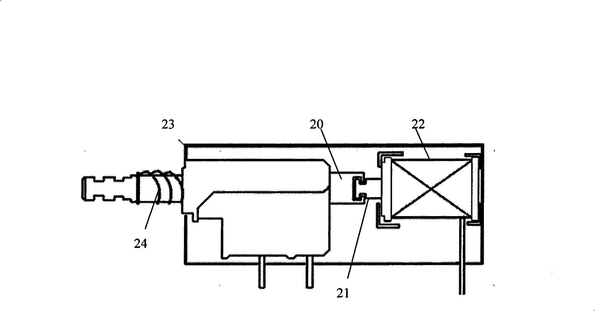
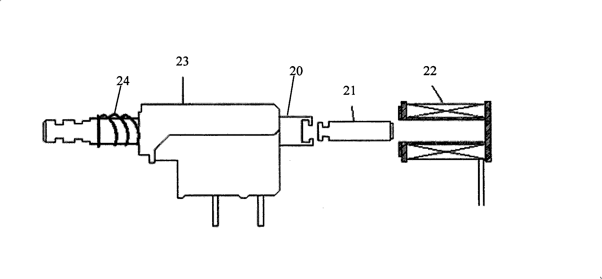
[0045] Such as Figure 1A and 1B As shown, the manual and pulse current control power switch of the present invention is improved on the basis of the general-purpose self-locking key power switch. A general-purpose push-button power switch generally consists of a push rod 20, a spring 24, a spring positioning piece, a switch contact, a self-locking guide rail, a self-locking shrapnel and a switch body 23. In the present invention, the tail of the push rod 20 of the existing general-purpose push-button power switch is lengthened so that it protrudes from the switch...


PUM


Abstract

The invention relates to a power switch for realizing zero standby power consumption and a control device. The control device comprises an SCM and a power switch connected between controlled equipment and an input power; the interior of the power switch is provided with a coil and an iron core. After the SCM receives the instruction of startup or shutdown, an instant impulse signal is output for controlling the conduction of a drive switch; an instant impulse current is generated in the coil of the power switch; the iron core under the effect of the magnetic force generated by the coil connects or disconnects the input power of the controlled equipment. Aiming at solving the disadvantage that the realization of zero standby power consumption increases extra power consumption of the prior art in normal working hours, thereby being unable to realize real effect of energy saving, the invention provides the power switch for realizing zero standby power consumption and the control device, and therefore, in standby state or in normal working state, no current passes through the coil of the power switch, realizing real zero power consumption and energy saving.

Description

technical field [0001] The invention relates to household appliances, more specifically, to a power switch and a control device for realizing zero-power consumption standby. Background technique [0002] In the current household appliances such as TV sets, users mostly turn off the power through the remote control, which is what we often call "standby". In this case, the power supply, remote control receiving and microprocessor parts in the machine still keep working to ensure that the electrical appliances can be woken up from the remote control or the light touch button on the machine next time. The power supply and microprocessor are designed for the whole system under full load, and the power consumption after standby is still maintained at a relatively high level. In addition, the circuit of the whole machine is connected to the power grid when it is in standby, so there are certain safety hazards, such as fire or explosion caused by lightning strike or overvoltage. R...

Claims


Application Information

Patent Timeline
IPC IPC(8): H01H13/50H01H13/20H01H3/28G05B19/042
Inventor 袁想平
Owner 袁想平
Why Eureka
Try Eureka