
Laminated rotor for high-speed motor

A high-speed motor, laminated technology, applied in the direction of electric components, electrical components, electromechanical devices, etc., can solve the problems of motor limit speed restriction, increase, solid rotor iron loss, rotor surface loss, etc., to achieve volume weight and cost reduction , Improve power density and reduce iron loss

Inactive Publication Date: 2008-12-24
XIANGTAN ELECTRIC MFG CORP LTD
View PDF0 Cites 8 Cited by
  • Summary
  • Abstract
  • Description
  • Claims
  • Application Information

AI Technical Summary

Problems solved by technology

However, due to the limitation of the mechanical strength of the rotor, the limit speed of the motor is also restricted. In the past, the linear speed of the laminated rotor of the motor was generally within 100m / s
Of course, there are also solid forged rotor structures to increase the motor speed (such as turbo generators), but the solid rotor iron loss (or rotor surface loss) is relatively large, and the manufacturing time (especially the processing of the tooth groove) and cost Compared with laminated rotors, the design of high-speed laminated rotors has become a key issue in the development of high-speed, high-performance motors; and the tangential stress of the inner holes of the laminates is often an important factor that limits the further increase in speed; in addition, other components on the rotor For example, the stress of winding ends, slot wedges, etc. at high speeds must also be carefully considered

Method used


Image

  • Laminated rotor for high-speed motor

Examples


Embodiment Construction

[0012] The present invention will be further described below in conjunction with the accompanying drawings and embodiments.

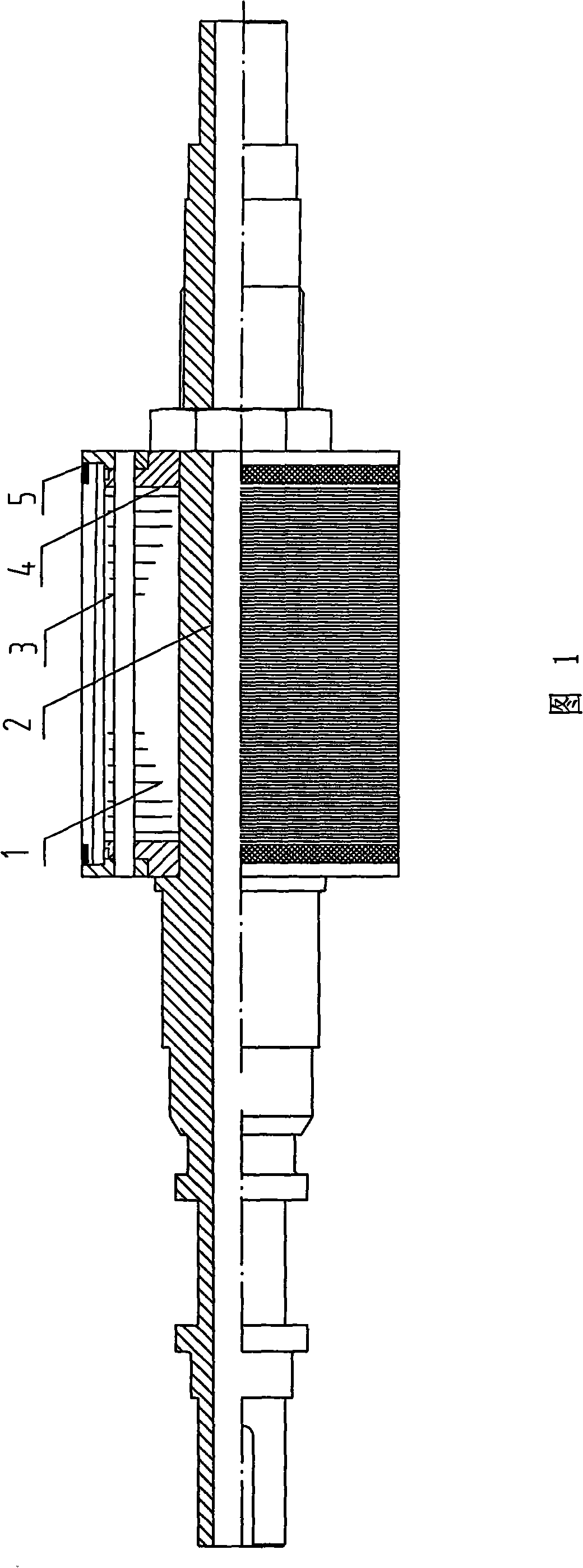
[0013] With reference to the accompanying drawings, this embodiment includes a lamination 1 made of magnetically permeable silicon steel sheet or a magnetically permeable steel plate, a hollow or solid shaft 2, two ends of the lamination 1 are provided with a pressure plate 4, and the lamination 1 and the pressure plate 4 pass through the pull rod 3 Tensioned into one body, the lamination 1 and the pressure plate 4 are provided with axial ventilation holes and grooves for installing guide bars, and the end of the winding is fixed by a weft-free tape 5; the inner hole of the lamination 1 and the outer diameter of the rotating shaft 2 are interference fit, The interference fit is 0.030-0.033mm. The inner hole of the pressure plate 1 and the outer diameter of the rotating shaft 2 also adopt an interference fit. In the above embodiment, the outer circular s...


PUM


Abstract

The invention provides a laminated rotor used for high-speed motors, which comprises a laminated sheet made from magnetic-permeable silicon steel sheets or magnetic-permeable steel plates and a solid or hollow rotating shaft, wherein press plates are respectively arranged at two ends of the laminated sheet. The laminated sheets are tensioned with the press plates as a whole via a draw bar. Axial air holes are formed on the laminated sheets and the press plates respectively. A groove is formed on the outer circumference of the laminated sheets and used for allowing a winding or a conductor to be embedded therein. The end parts of the winding are fixed by a weftless tape or a steel hoop. The inner hole of the laminated sheets and the outer diameter of the rotating shaft adopt a keyless interference fit. The inner hole of the press plates and the outer diameter of the rotating shaft also adopt a keyless interference fit. The interference value is determined based on the actual interference fit and stress and is different to the products with different specifications. The linear speed of the laminated rotor is as high as more than 200m / s. The iron loss of the rotor is reduced while the rotational speed of the motor is increased, that is, the power density of the motor is increased. Additionally, compared with the solid rotor, the manufacturing time and cost of the laminated rotor are greatly reduced. The laminated rotor is suitable for the high-speed asynchronous motor as well as the high-speed non-salient-pole synchronous motor and the non-commutator direct current motor.

Description

technical field [0001] The invention relates to a laminated rotor for a high-speed motor, in particular to a laminated rotor suitable for frequency conversion and speed regulation asynchronous motors, high-speed hidden-pole synchronous motors or DC motors without commutators. Background technique [0002] According to the relevant theory of the motor, under the condition of constant power, the volume of the motor is almost inversely proportional to the speed. Therefore, increasing the speed of the motor is an effective way to increase the power of the motor and reduce the volume of the motor. However, due to the limitation of the mechanical strength of the rotor, the limit speed of the motor is also restricted. In the past, the linear speed of the laminated rotor of the motor was generally within 100m / s. Of course, there are also solid forged rotor structures to increase the motor speed (such as turbo generators), but the solid rotor iron loss (or rotor surface loss) is rela...

Claims


Application Information

Patent Timeline
Patent Type & Authority Applications(China)
IPC IPC(8): H02K1/22H02K1/28H02K1/26H02K3/51H02K1/32
Inventor 胡国恒陈震林陈雷陈建锋
Owner XIANGTAN ELECTRIC MFG CORP LTD
Learn More