Argon-blowing spray gun for refining ladle and making method thereof

A technology of ladle refining and spray gun, which is applied in the field of ladle refining argon blowing spray gun and its preparation, which can solve the problems of poor stirring effect and low service life of the spray gun

Inactive Publication Date: 2009-01-07
武钢集团有限公司 +1
View PDF3 Cites 6 Cited by
  • Summary
  • Abstract
  • Description
  • Claims
  • Application Information

AI Technical Summary

Problems solved by technology

[0003] The technical problem to be solved by the present invention is to solve the problems of low service life of the spray gun and poor stirring effect

Method used


Image

  • Argon-blowing spray gun for refining ladle and making method thereof
  • Argon-blowing spray gun for refining ladle and making method thereof
  • Argon-blowing spray gun for refining ladle and making method thereof

Examples


Embodiment 1

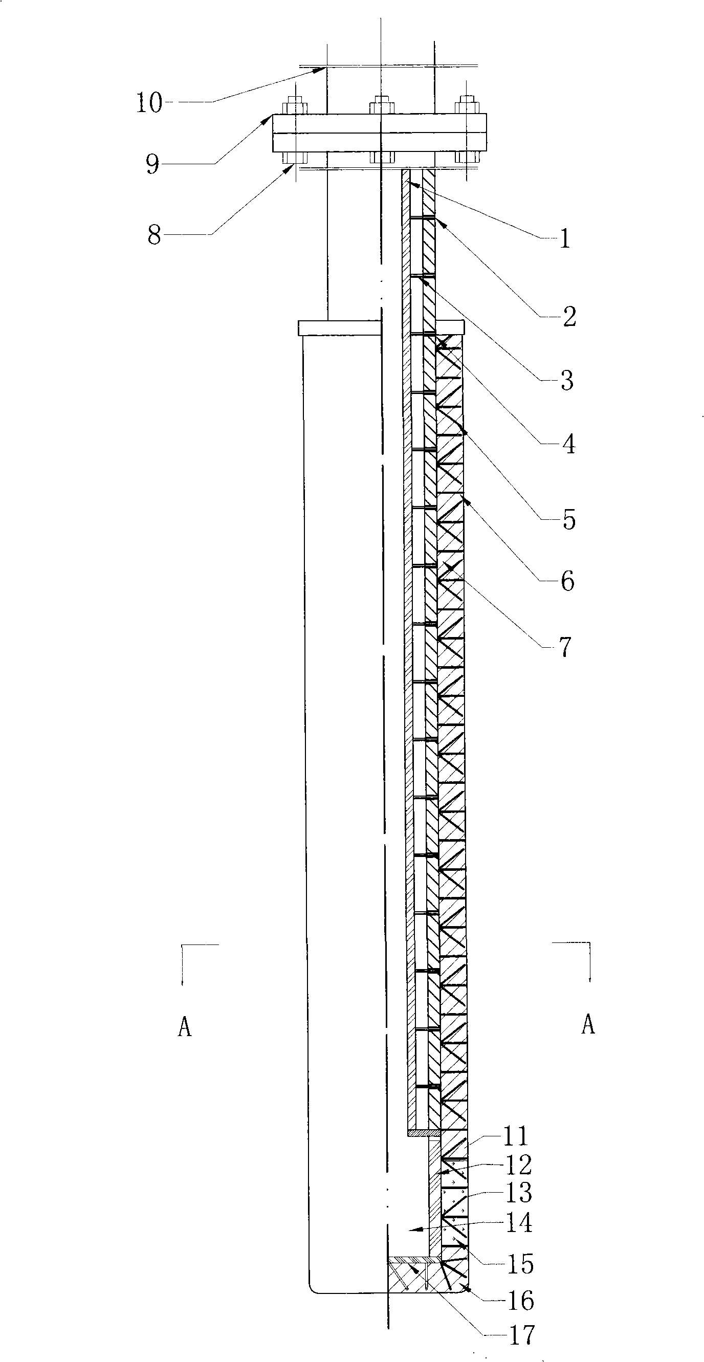
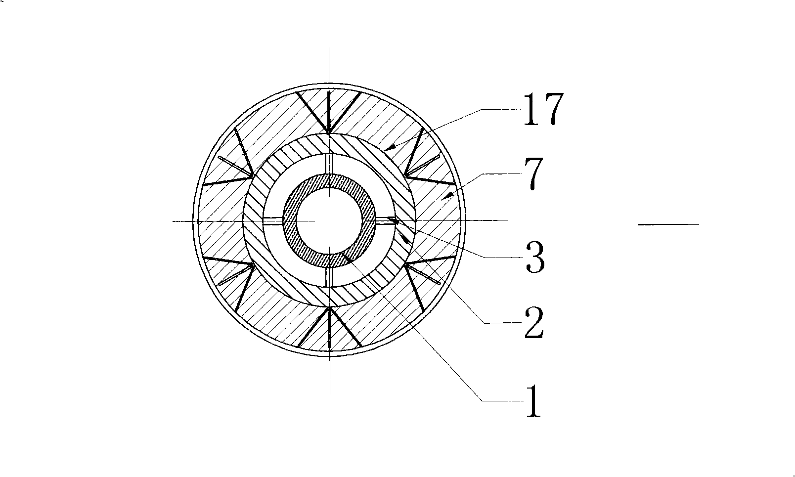
[0023] Such as figure 1 , image 3 Shown, the present invention comprises metal gun shaft 10 and spray gun body, and the bottom end of metal gun shaft 10 and the top end of spray gun body are provided with connecting flange 9 respectively, metal gun shaft 10 and spray gun body are connected together by connecting bolt 8, the spray gun body The lower part is provided with a diffusion nozzle 11 . The spray gun body includes a main pipe 1, a reinforcing pipe 2, a number of bridging weldments 3, a number of rivets and a refractory working lining 7, the main pipe 1 and the reinforcing pipe 2 are ordinary carbon steel seamless steel pipes, and the reinforcing pipe 2 is set outside the main pipe 1 , and a number of bridging weldments 3 are evenly welded between the main pipe 1 and the reinforcing tube 2, the bridging welding pieces 3 are short steel columns shearing rebar or carbon steel wire rods, with a diameter of 8mm; the outer circumference of the reinforcing tube 2 is covered ...

Embodiment 2

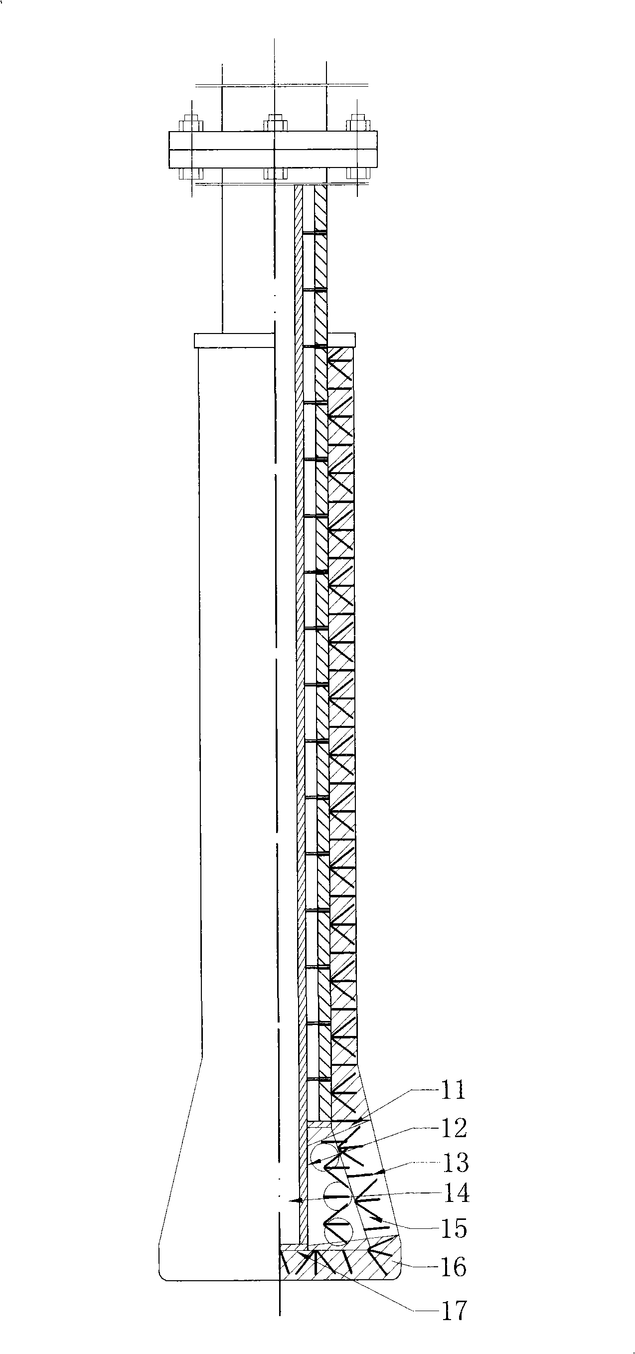
[0028] Such as figure 2 as shown, figure 2 It is a schematic diagram of the structure of this embodiment. The difference between this embodiment and Embodiment 1 is that the diffuse nozzle 11 is in the shape of a truncated cone with a small top and a large bottom, and the diffuse nozzle 15 is in the shape of a capillary hole and is inclined upward with a plane perpendicular to the longitudinal axis of the metal tube 12. 2 to 5 degrees. The upper end of the metal pipe 12 is connected to the spray gun reinforcement pipe 2 by welding, or the metal pipe 12 and the reinforcement pipe 2 are the same pipe.

[0029] The shape of the diffusion nozzle 11 of the present invention is not limited to the shape defined in Embodiment 1 and Embodiment 2, and can also be hemispherical or semi-ellipsoidal. At this time, the diameter of the bottom surface of the diffusion nozzle 11 is greater than or equal to the top surface diameter and the outer surface of the diffusion nozzle 11 and the o...


PUM

PropertyMeasurementUnit
diameteraaaaaaaaaa

Abstract

The invention discloses an argon blowing lance which includes a metal lance rod and a lance body that are connected together by a flange; the lower part of the lance body is provided with a dispersion nozzle; the lance body includes a main tube, a reinforcing tube, a plurality of bridging welding pieces, a plurality of rivet pieces and the working liner of a fire-proof material; the reinforcing tube is sheathed on the outside of the main tube; besides, a plurality of bridging welding pieces are uniformly welded between the reinforcing tube and the main tube; the rivet pieces of V shape and double V-shape are respectively and alternatively arranged in the working liner of the fire-proof material outside the reinforcing tube along the surrounding direction and the coaxial direction of the reinforcing tube; besides, the top points of the two are respectively welded with the outer surface of the reinforcing tube. The measures of the invention of sheathing the reinforcing tube and the bridging welding pieces outside the main tube of the core of the lance improve the intensity and the rigidness of the core structure of the lance; the rivet pieces of V shape and double V-shape enhance the bonding intensity between the core of the metal core of the lance and the working liner of the fire-proof casting material; the dispersion nozzle improves the blowing stirring intensity and finally achieves the goals of prolong the service life of the lance and improving the use performance of the lance.

Description

technical field [0001] The invention relates to a ladle refining argon blowing spray gun and a preparation method thereof, in particular to an argon blowing spray gun for molten steel refining and a preparation method thereof. Background technique [0002] The argon blowing lance is an important component in steelmaking and refining equipment, and its service life and stirring effect have a direct impact on the steel type and quality. According to the argon-blowing process, the argon-blowing spray gun must not only withstand the erosion and erosion of high-temperature molten steel and slag during intermittent use, but also withstand large temperature changes. Therefore, the argon-blowing spray gun should have good mechanical properties at high temperatures, Stable volume, not easy to peel off, anti-corrosion and other characteristics. The argon-blowing spray guns used in the early days had a combined sleeve brick structure, that is, a number of sleeve bricks were assembled ...

Claims


Application Information

Patent Timeline
Patent Type & Authority Applications(China)
IPC IPC(8): C21C7/072
Inventor 欧阳德刚李具中蒋扬虎彭玮坷吴杰罗安智胡清明曾彤袁凡成王海清
Owner 武钢集团有限公司
Why Eureka
Try Eureka