Hot pipe type porous foamed metal heat exchanger

A porous metal foam, heat pipe technology, applied in indirect heat exchangers, lighting and heating equipment, etc., can solve the problems of high metal consumption, small heat transfer area, heavy equipment weight, etc., to achieve small size and wide range of uses. , compact structure

Inactive Publication Date: 2009-01-07
NANJING UNIV OF TECH
View PDF0 Cites 20 Cited by
  • Summary
  • Abstract
  • Description
  • Claims
  • Application Information

AI Technical Summary

Problems solved by technology

[0003] The purpose of the present invention is to solve the problem that the existing heat pipe has a small heat transfer area, which makes the equipment heavy in weight, large in size, and consumes a lot of metal. Substantially reduced heat pipe type porous metal foam heat exchanger

Method used


Image

  • Hot pipe type porous foamed metal heat exchanger

Examples


Embodiment Construction

[0015] The present invention will be further described below in conjunction with the accompanying drawings and embodiments.

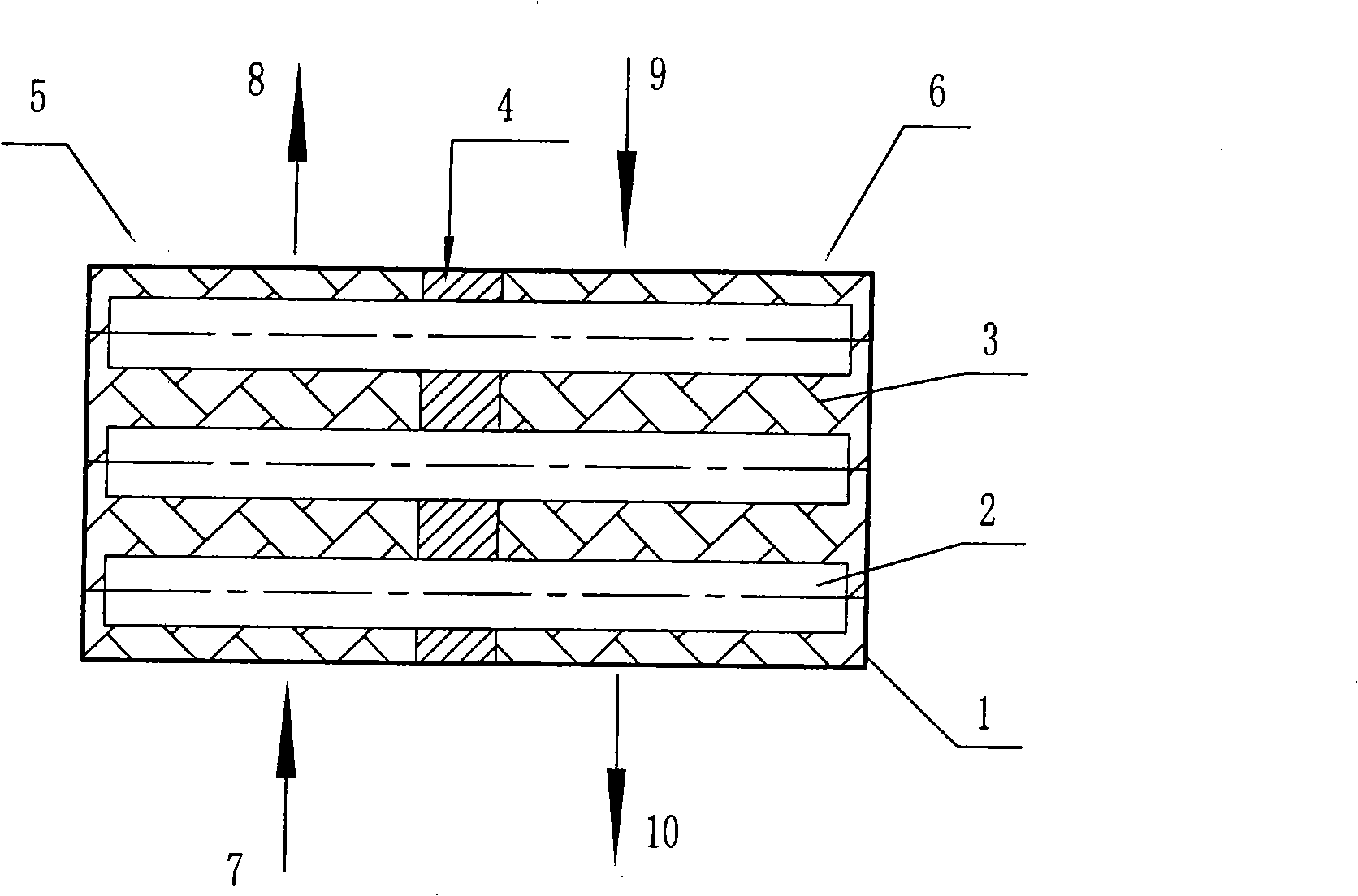
[0016] Such as figure 1 shown.

[0017] A heat pipe type porous metal foam heat exchanger, including a shell 1, a heat pipe 2 and a heat insulation plate 4, the heat insulation plate 4 is installed in the shell 1 to divide the shell 1 into a hot fluid exchange area 5 and a cold fluid exchange area 6 , the heat pipe 2 is installed in the housing 1 through the heat insulation board 4, one end of which is located in the hot fluid exchange area 5, and the other end is located in the cold fluid exchange area 6, and the housing 1 is provided with corresponding hot fluid inlet and outlet 7 , 8 and cold fluid inlet and outlet 9,10, in the hot fluid exchange area 5 and the cold fluid exchange area 6 of the shell 1, the surroundings of the heat pipe 2 are all filled with porous metal foam 3, and the surface of the heat pipe 2 and the porous metal foam 3 In suff...


PUM


Abstract

The invention discloses a heat pipe multihole foam metal heat exchanger with multihole foam metal as expanded transfer area based on the heat pipe principle, in order to solve the problems of the prior heat pipe heat exchanger with expanded transfer area, namely, large volume, large weight, consuming much metal and so on. The heat pipe multihole foam metal heat exchanger solves the problem of small heat interchanging area of heat pipes through filling multihole foam metal around the heat pipes in a shell. Cold and hot fluid involving in transfer of heat flows through multihole foam metal passages. Therefore, the heat exchanger is lighter, smaller and more compact with less metal consumed under the precondition of the same heat exchange effect.

Description

technical field [0001] The invention relates to a heat exchange device, in particular to a heat pipe type heat exchanger, in particular to a heat pipe type porous foam metal heat exchanger using a heat pipe as a heat transfer element and a porous foam metal as an extended heat transfer surface. Background technique [0002] As we all know, using heat pipes as heat exchange devices is a common means of heat exchange. Since the surface area of ​​heat pipes is relatively fixed, in order to increase the heat exchange effect and expand the heat exchange area, at present, the method used to expand the heat transfer surface on the outer surface of the heat pipe is usually It is to add welding straight fins or spiral fins on the outer surface of the heat pipe to increase the heat transfer area, but the heat transfer area expanded by these methods is still very limited, and the metal consumption is relatively large, and the equipment is large in size and heavy in weight. Heavier, the...

Claims


Application Information

Patent Timeline
Patent Type & Authority Applications(China)
IPC IPC(8): F28D15/02
Inventor 李菊香涂善东
Owner NANJING UNIV OF TECH
Why Eureka
Try Eureka