Optical fibre mode converter

A mode converter and optical fiber technology, which is applied in cladding optical fiber, optical waveguide and light guide, etc., can solve the problems affecting the performance of optical fiber devices, and achieve the effect of competitive and easy mass production

Inactive Publication Date: 2009-01-07
JIANGSU UNIV
View PDF0 Cites 25 Cited by
  • Summary
  • Abstract
  • Description
  • Claims
  • Application Information

AI Technical Summary

Problems solved by technology

Since in the above several optical fiber devices, only one mode is required in the optical fiber, so as to realize single-mode transmission in another sense, the remaining energy will interfere with the transmitted optical signal, thereby affecting the performance of the optical fiber device

Method used


Image

  • Optical fibre mode converter
  • Optical fibre mode converter
  • Optical fibre mode converter

Examples


Embodiment 1

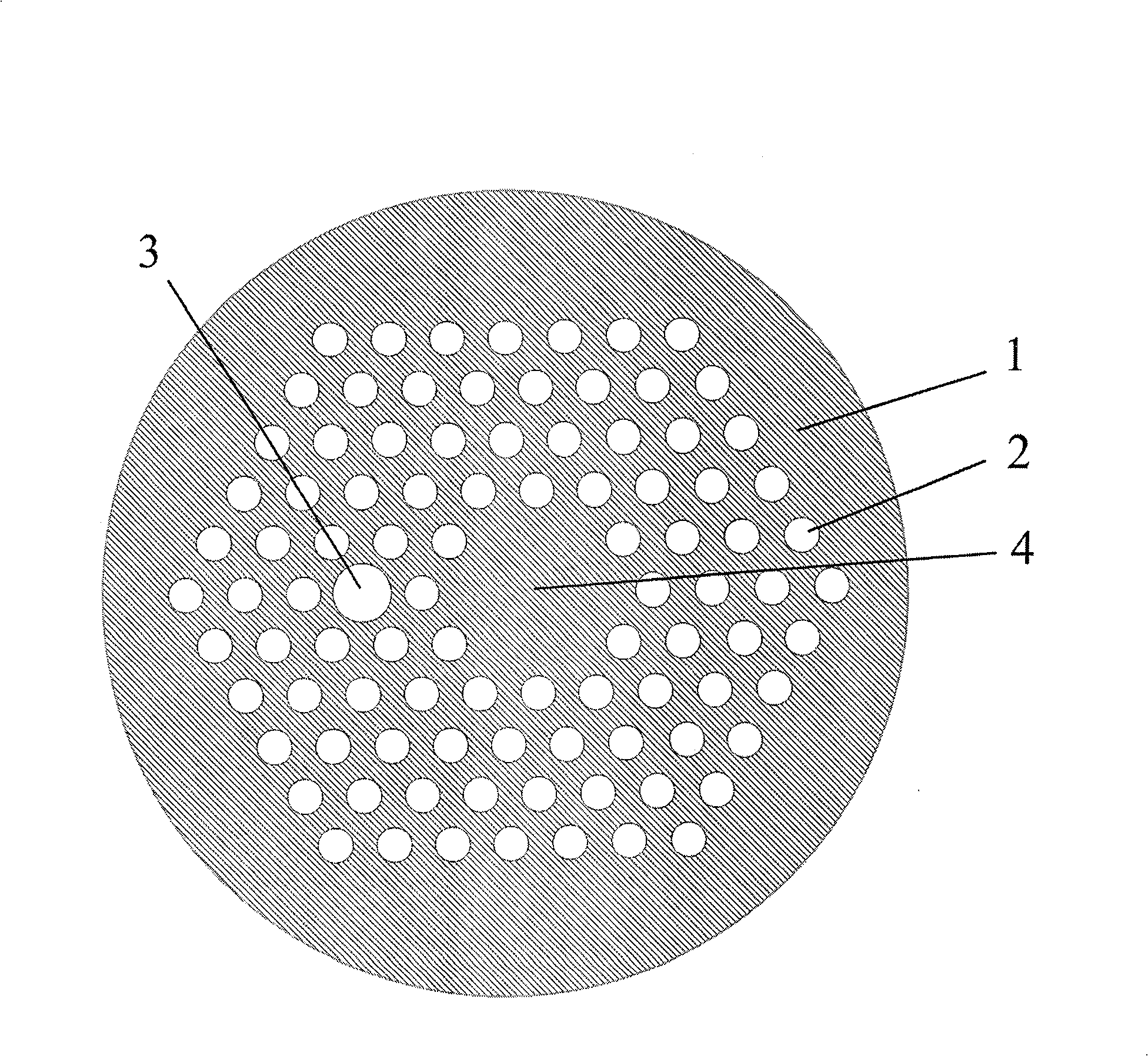
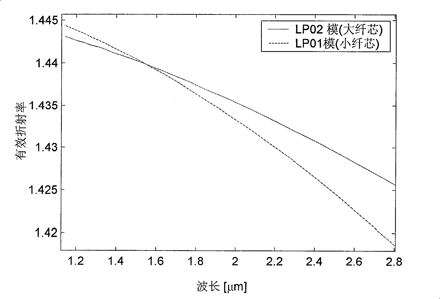
[0019] Such as figure 1 As shown, the matrix material 1 of the dual-core photonic crystal fiber is pure silica, the diameter d of the air holes 2 is 2.28 μm, and the hole spacing is taken as Λ=4.56 μm. The small core 3 is composed of doped silica, which has a refractive index 0.004 lower than that of pure silica. The large core 4 is composed of 7 missing air holes. The working wavelength is 1.55μm, and the fiber length is 12.7mm. figure 2 for figure 1 LP with small core in the structure shown 01 LP in mode and large core 02 Schematic diagram of the effective refractive index of a mode as a function of wavelength. The two curves intersect at this 1.55 μm, therefore, the LP of the small core at this wavelength 01 LP in the core of the mode and large 02 Modes will undergo periodic energy coupling. Taking the fiber length as the coupling length of the two, that is, 12.7mm, the purpose of mode conversion can be achieved. Using different fiber structure parameters, small c...


PUM


Abstract

The invention provides an optical fiber mode converter for realizing the conversion between modes, and the optical fiber mode converter is a twin-core photonic crystal fiber, comprising a matrix material and a cladding and fiber cores formed by air vents. The converter is characterized in that two fiber cores are of different sizes, wherein, the smaller fiber core is used for transmitting a basic mode, whereas the larger fiber core is used for transmitting a high-order mode; the effective refractive index of the basic mode of the smaller fiber core is equal to that of the corresponding high-order mode of the larger fiber core at an operating wavelength position. The optical fiber mode converter of the invention uses the energy coupling between the basic mode and the high-order mode of the two fiber cores to realize the conversion between the basic mode and the high-order mode, which ensures a purer conversion mode. Meanwhile, as a twin-core photonic crystal fiber structure is adopted, the converter has no particular requirements in manufacturing technology, and can be put into mass production easily, thus possessing better competitive strength when compared with a converter that adopts a fiber grating.

Description

technical field [0001] The invention relates to the field of optical fiber communication, in particular to an optical fiber mode converter capable of realizing conversion between modes. Background technique [0002] Since single-mode fiber can avoid the intermodal dispersion problem of multi-mode fiber transmission, it is currently the most widely used single-mode fiber in the fields of communication and sensing. In recent years, many new optical fiber structures have also been proposed. For example, the Bragg fiber adopting the principle of photonic bandgap, the mode with the lowest transmission loss is not the LP of ordinary single-mode fiber 01 Die, but TE 01 model [Optics Express, 2001, 9(13), 748]. In addition, it is also proposed to use high-order modes to realize dispersion compensation technology [Journal of Lightwave Technology, 2005, 23(11), 3426] and to convert fundamental mode light into high-order modes [OpticsLetters, 2006, 31(12), 1797], so as to realize la...

Claims


Application Information

Patent Timeline
Patent Type & Authority Applications(China)
IPC IPC(8): G02B6/14G02B6/02
Inventor 陈明阳余学权周骏
Owner JIANGSU UNIV
Why Eureka
Try Eureka