Non-etched flat polarization-selective diffractive optical elements

A technology of diffractive optical elements and linearly polarized light, applied in polarizing elements, optical elements, diffraction gratings, etc., can solve the problems of time-consuming, complicated etching and/or molding steps, etc.

Inactive Publication Date: 2009-01-07
JDS UNIPHASE CORP
View PDF6 Cites 26 Cited by
  • Summary
  • Abstract
  • Description
  • Claims
  • Application Information

AI Technical Summary

Problems solved by technology

Unfortunately, the etching and / or molding steps used to form these diffractive optical elements are relatively complex and time-consuming

Method used


Image

  • Non-etched flat polarization-selective diffractive optical elements
  • Non-etched flat polarization-selective diffractive optical elements
  • Non-etched flat polarization-selective diffractive optical elements

Examples


Embodiment Construction

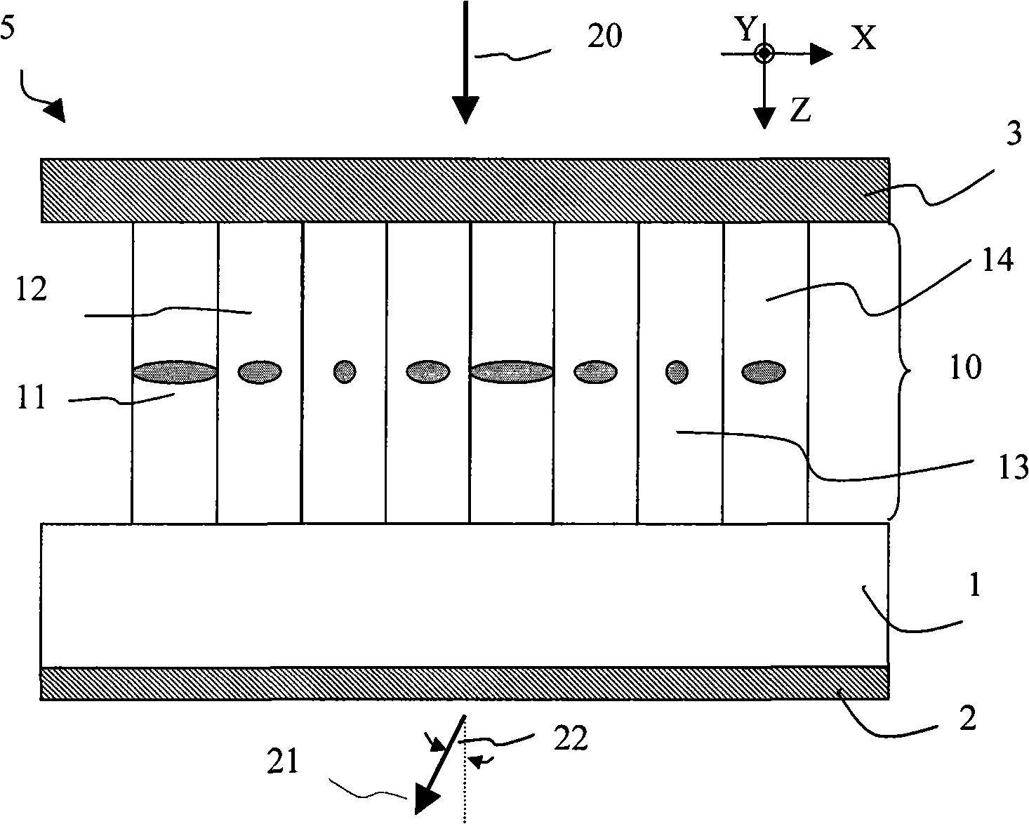
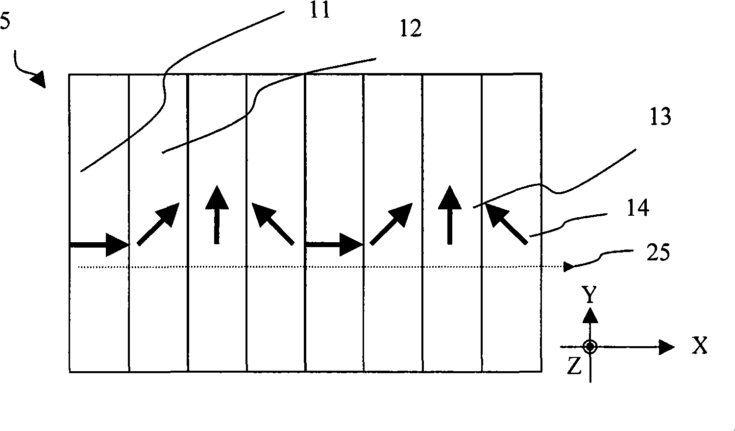
[0065] [63] A prior art thin film liquid crystal (LC) hologram structure is shown in Figure 1, which is a thickness cross-sectional view along the grating vector. The grating vectors are the planes where light is scattered by diffraction effects. The grating vector is also the pixelation direction of the 1D grating or hologram. holographic Figure 5 Comprising a substrate 1 on which is arranged a pixel array 10 with LC director orientations with variable azimuthal angles. The LC director orientations for four discrete azimuthal angles are shown in 11 , 12 , 13 and 14 . More specifically, the projection of the LC refractive index characteristic curve on the drawing plane (XZ plane) is shown. Pixel 11 has a projected director aligned parallel to the X-axis, while pixel 13 has a projected director aligned parallel to the Y-axis. The other two states, pixels 12 and 14 have projected directors contained in the XY plane, but not parallel to the X and Y axes. The hologram elemen...


PUM

PropertyMeasurementUnit
thicknessaaaaaaaaaa
widthaaaaaaaaaa

Abstract

The invention relates to a polarization-selective diffractive optical element that includes a liquid crystal polymer film supported by a substrate. The liquid crystal polymer film includes an array of pixels, each pixel encoded with a fixed liquid crystal director such that each liquid crystal director is aligned in a common plane perpendicular to the liquid crystal polymer film and provides a predetermined pattern of out-of-plane tilts. A size of the pixels in the array and the predetermined pattern are selected such that the liquid crystal polymer film forms a phase hologram for diffracting light polarized parallel to said common plane and a zeroth order diffraction grating for light polarized perpendicular to the said common plane. The non-etched and flat phase hologram is suitable for a wide range of applications.

Description

[0001] Cross References to Related Applications [0002] [01] This application claims priority to US Provisional Application No. 60 / 947,690, filed July 3, 2007, which is hereby incorporated by reference. [0003] Microfiche Addendum [0004] [02] Not applicable technical field [0005] [03] The present application relates generally to diffractive optical elements, and more particularly to a non-etched and plane polarization selective diffractive optical element. Background technique [0006] [04] Diffraction gratings encoded on programmable liquid crystal (LC)-based spatial light modulators (SLMs) and more complex thin-film holograms have been actively investigated as a means of modifying the wavefront of a beam of light. For example, these LC / SLMs can be used for adaptive optical phase correction in synthetic phase antenna arrays or communication beam steering switches. LC / SLMs are typically based on transmissive or reflective type microdisplay panels to provide small p...

Claims


Application Information

Patent Timeline
Patent Type & Authority Applications(China)
IPC IPC(8): G02F1/1337G02B5/18G11B7/135
CPCG11B7/13925G02F1/13342G03H2240/23G02B5/1871G03H2250/38G03H2240/11G02F2203/07G11B2007/0006G02F1/133753G02B5/32G02B5/3016G11B7/1353G02B5/30G02F1/1337
Inventor 谭金龙大卫·M.·西蒙
Owner JDS UNIPHASE CORP
Why Eureka
Try Eureka