Wireless remote control method

A wireless remote control and remote control system technology, applied in signal transmission systems, instruments, data exchange through path configuration, etc., can solve the problems of inability to control multiple different types of receivers, small number of address codes, non-compliance, etc., to achieve Easy to network and expand, reduce complexity, and avoid hijacking effects

Inactive Publication Date: 2009-01-14
JIANGSU HUITONG GRP
View PDF0 Cites 30 Cited by
  • Summary
  • Abstract
  • Description
  • Claims
  • Application Information

AI Technical Summary

Problems solved by technology

[0003] Fixed-code and rolling-code remote control devices have their own characteristics. Fixed-code chips are cheap, but the number of address codes is small. For example, the most used PT2262 on the market has only 6561, and the probability of repeated codes is high.
Rolling coding chip has low probability of recoding and good anti-cracking performance, but the price is more expensive, and it must be "code-checked" before it can be put into work, which is relatively troublesome
[0004] The above-mentioned remote control method also has the following disadvantages: 1. The data of the receiving end and the sending end are pre-written in the program, which is not easy to change, and d

Method used


Image

  • Wireless remote control method
  • Wireless remote control method
  • Wireless remote control method

Examples


Embodiment 1

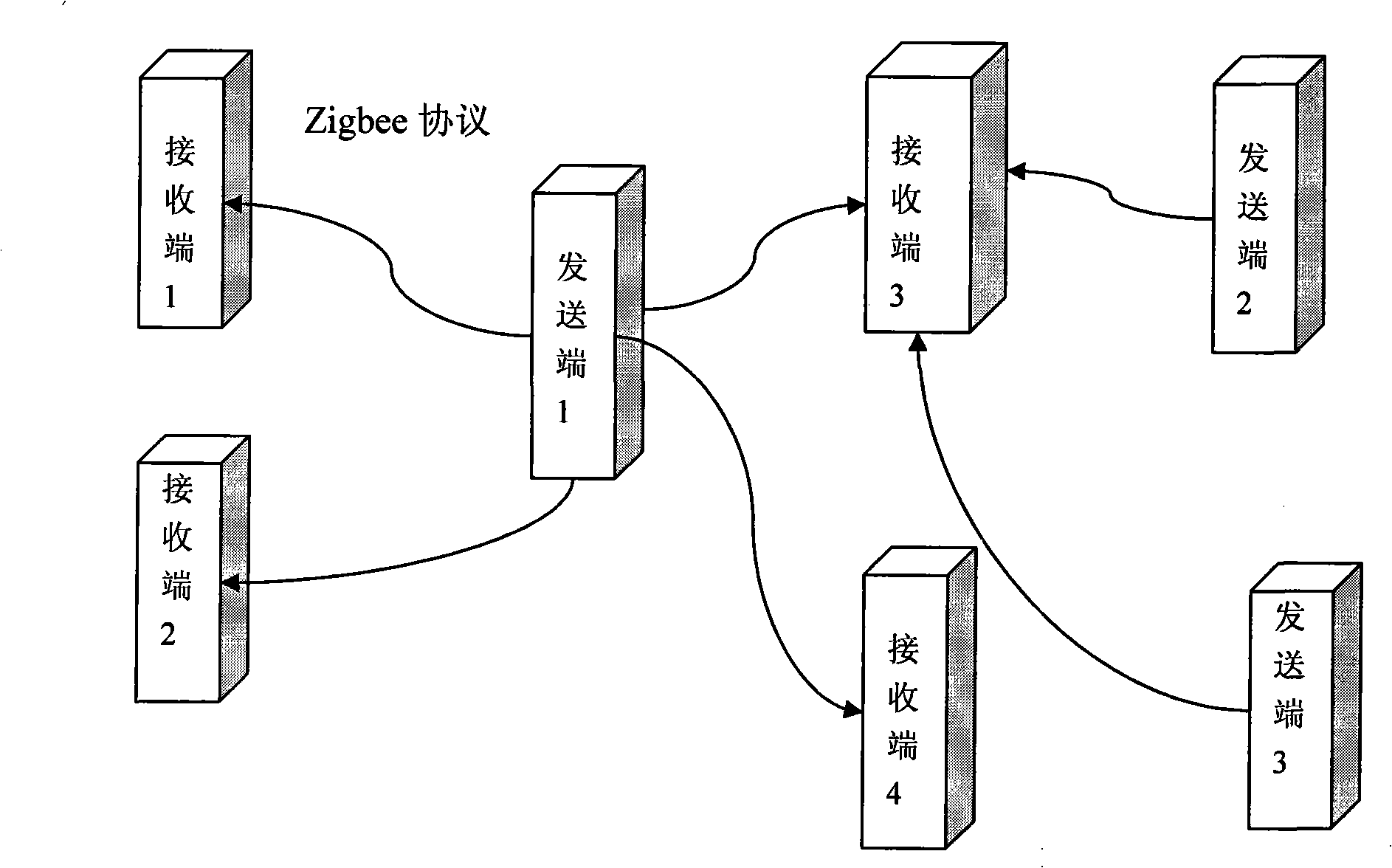
[0052] Such as figure 1 As shown, 2 transmitters and 4 receivers form a wireless sensor network according to the Zigbee protocol.

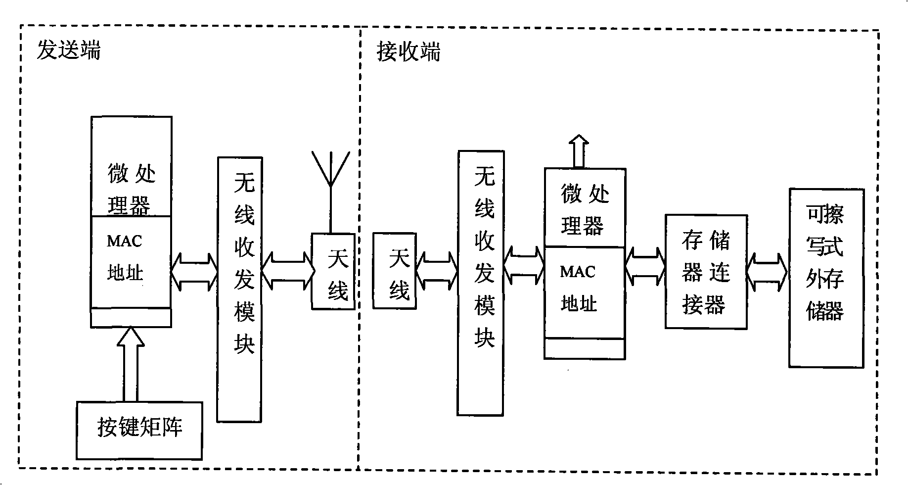
[0053] Such as figure 2 As shown, the sending end is equipped with a microprocessor chip, a keyboard, a wireless transceiver module and an antenna, and the keyboard is connected to the I / O port of the chip through a matrix, and is accessed through a normal I / O port. The receiving end is provided with a microprocessor chip, a mobile erasable memory (EPROM), a memory interface, a wireless transceiver module and an executing mechanism.

[0054] The bottom layer of the sending end and the receiving end is based on the Zigbee protocol, and the entire architecture and protocol are compatible with Zigbee products on the market. ZigBee technology is a two-way wireless communication technology with short distance, low complexity, low power consumption, low data rate, and low cost. It is mainly suitable for the fields of automatic control and remote cont...

Embodiment 2

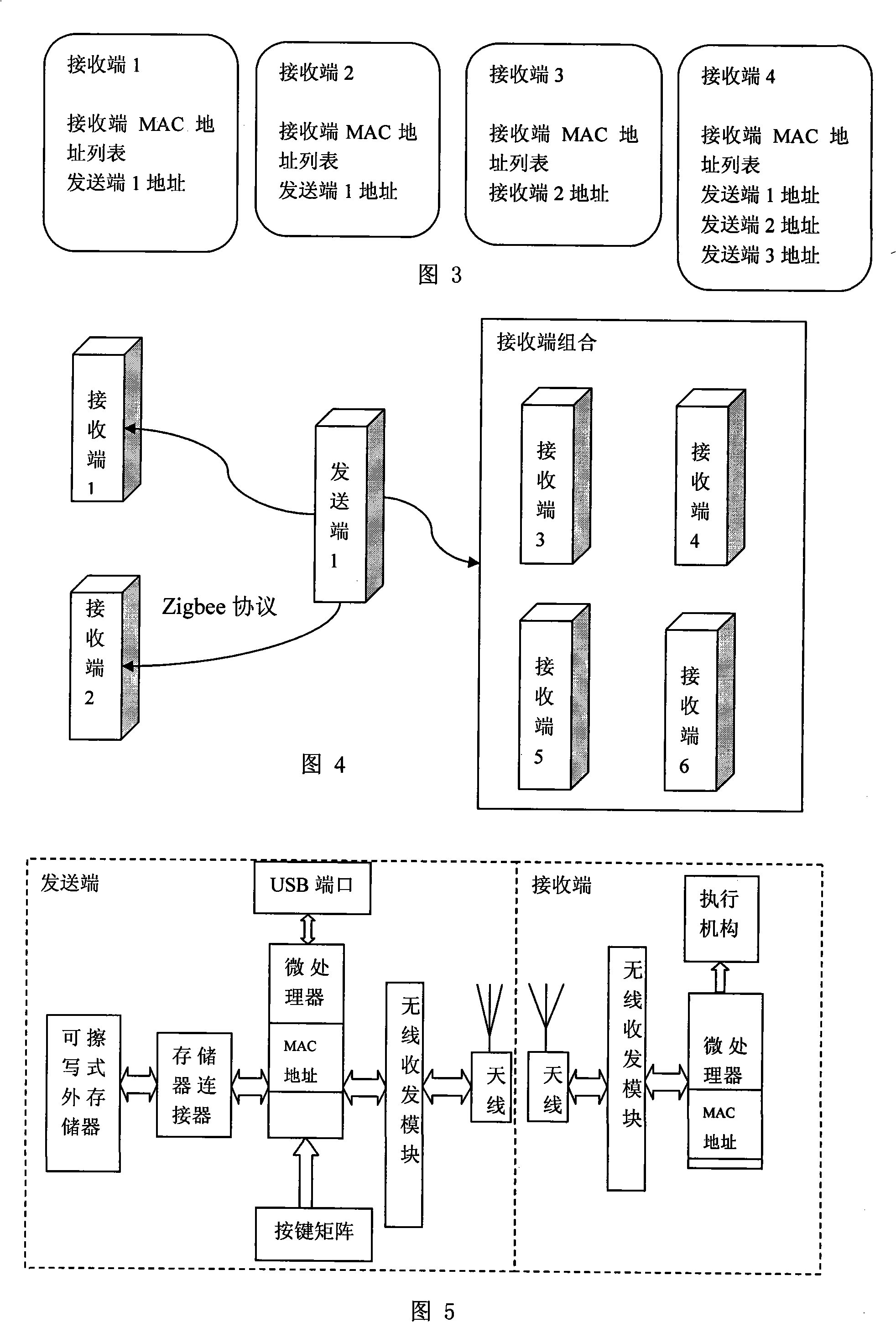
[0061] As shown in Figure 4, one transmitter and six receivers form a wireless sensor network according to the Zigbee protocol, and receiver 3, receiver 4, receiver 5, and receiver 6 form a receiver combination.

[0062] As shown in Figure 5, the sending end is equipped with a microprocessor chip, keyboard, removable erasable memory (EPROM), memory interface, wireless transceiver module and antenna, and the keyboard is connected to the I / O port of the chip through a matrix , through the normal I / O port access, the wireless transceiver module is connected to the microprocessor chip, the USB port is converted through UART, and a USB-to-serial port chip is used to send the serial port signal to the computer or other devices through the USB cable. The receiving end, computer or other receiving end can also wirelessly control the receiving end controlled by the sending end. The receiving end is provided with a microprocessor chip, a keyboard, a wireless transceiver module and an ex...

Embodiment 3

[0070] Such as Figure 7 , sending end 1, sending end 2, sending end 3, sending end 4, receiving end 1 to receiving end 6 form a wireless sensor network according to the Zigbee protocol, receiving end 3 is equipped with a router, receiving end 5 and receiving end 6 form a receiving end combination.

[0071] Such as Figure 8 , the sending end is equipped with a microprocessor chip, keyboard, removable erasable memory (EPROM), memory interface, wireless transceiver module, antenna and USB port, the keyboard is connected to the I / O port of the chip through a matrix, and the EPROM ) are accessed through normal I / O ports. The USB port is converted from UART. A USB-to-serial chip is used to send the serial signal to the computer or other receiving end through the USB cable. The computer or other receiving end can also wirelessly control the receiving end controlled by the sending end.

[0072] The receiving end is provided with a microprocessor chip, a keyboard, a mobile erasabl...


PUM


Abstract

The invention relates to a wireless remote-control method which includes the following steps: MAC addresses are respectively arranged for a transmitting terminal and a receiving terminal; microprocessor chips are respectively arranged at the transmitting terminal and the receiving terminal and the MAC addresses of the transmitting terminal and the receiving terminal are respectively written into the respective microprocessors; the MAC address information of the transmitting terminal is stored into the receiving terminal, while the MAC address information of the receiving terminal is stored into the transmitting terminal; the transmitting terminal transmits a controlling signal with the stored MAC address information of the receiving terminal; the transmitted MAC address is compared with the MAC address stored in the receiving terminal by the receiving terminal, if the transmitted MAC address is matched with the stored MAC address, the controlling signal is received and relative operation is carried out, otherwise, no operation is responded; the receiving terminal transmits a controlling signal with the MAC address information of the transmitting terminal to the transmitting terminal, and the transmitting terminal compares the transmitted MAC address of the receiving terminal with the stored MAC address of the receiving terminal, if the transmitted MAC address is matched with the stored MAC address, the controlling signal is received and relative operation is carried out, otherwise, no operation is responded.

Description

technical field [0001] The invention relates to the field of wireless remote control, in particular to a wireless remote control method. technical background [0002] Use the wireless method to complete the remote control operation. The common ones are wireless remote control switch light, wireless remote control various electric toys, wireless remote control door switch, switch lock, wireless remote control car anti-theft alarm and various industrial wireless remote control, etc. The wireless remote control is divided into two parts: sending and receiving. The sending part is the wireless remote control. Its principle is to encode the control command and send it out through modulation. After the receiving circuit receives the remote control signal, it obtains the control command through decoding, remote control coding and decoding. It is further divided into two types: fixed encoding and rolling encoding. Typical fixed encoding chips such as PT2262, V1526, RT6588, etc., typ...

Claims


Application Information

Patent Timeline
IPC IPC(8): G08C17/02H04L12/28
Inventor 刘正东龙江程明慧龙涛
Owner JIANGSU HUITONG GRP
Why Eureka
Try Eureka