Radiating structure of LED

A technology of light-emitting diodes and heat-dissipating structures, which is applied to semiconductor devices of light-emitting elements, light sources, point light sources, etc., can solve the problems of low luminous efficiency, large power consumption, poor heat dissipation, etc. The effect of prolonging life

Inactive Publication Date: 2009-01-21
刘雪峰
View PDF0 Cites 3 Cited by
  • Summary
  • Abstract
  • Description
  • Claims
  • Application Information

AI Technical Summary

Problems solved by technology

[0002] At present, the existing chip-packaged light-emitting diodes on the market have low luminous efficiency,

Method used


Image

  • Radiating structure of LED
  • Radiating structure of LED
  • Radiating structure of LED

Examples


Example Embodiment

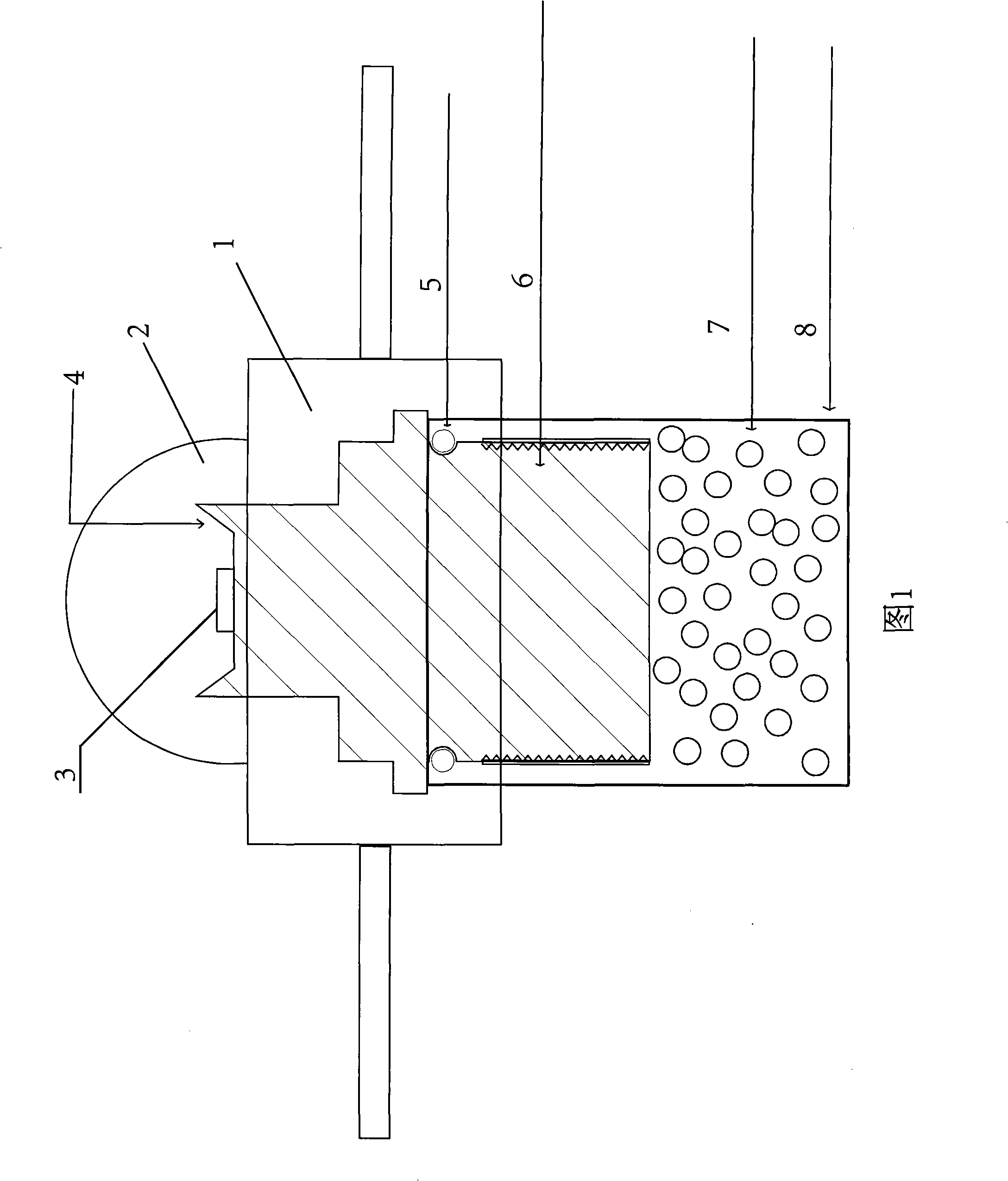
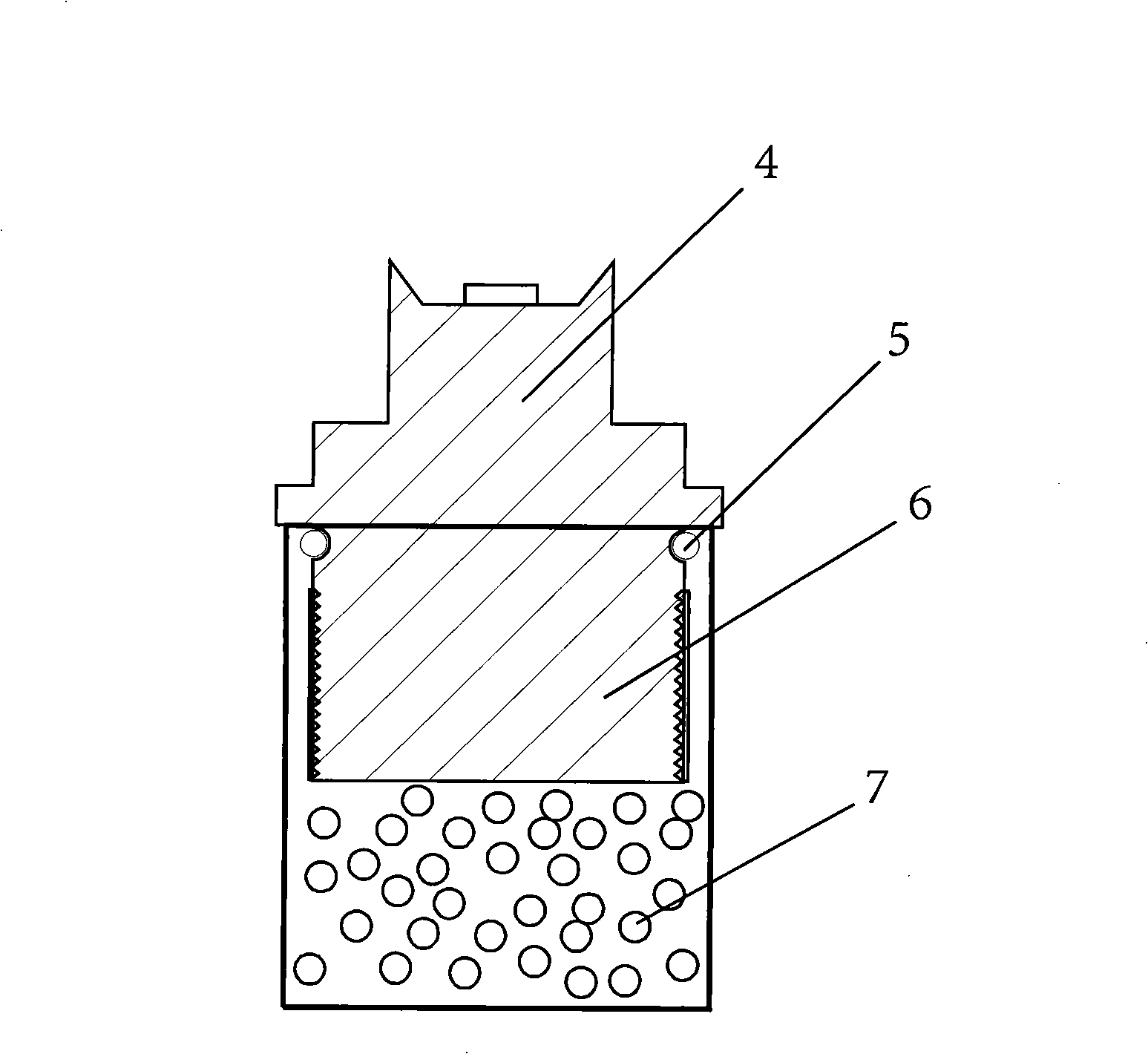
[0013] Fig. 1 is an overall assembly diagram of the heat dissipation structure of the light emitting diode of the present invention.

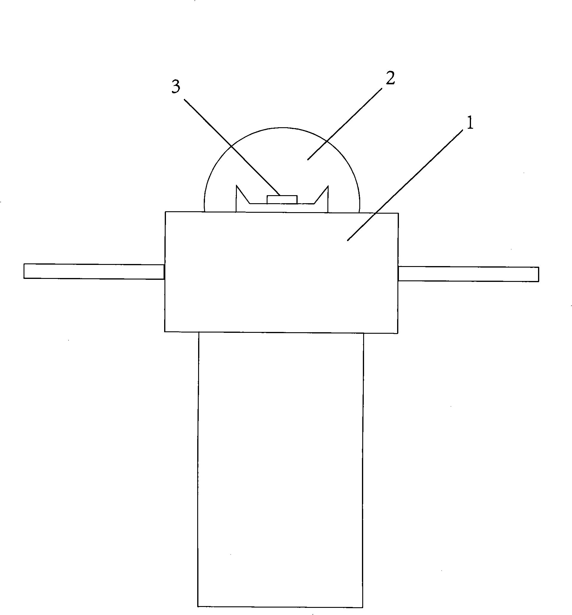
[0014] In the figure, the light-emitting diode heat dissipation structure includes a metal casing 1, a packaging cover 2, a light-emitting diode 3, a mirror reflector 4, an anti-leakage silicone rubber 5, a mirror reflective solid crystal heat conduction bracket 6, and a heat dissipation coolant 7. The metal casing 1 is the casing of the light-emitting diode, which is used to dissipate the heat emitted by the light-emitting diode when it is working. The packaging cover 2 is on the top of the metal shell 1 for packaging the light emitting diode 3. The light emitting diode 3 is located in the center of the mirror reflector 4. The mirror surface reflector 4 is on the upper part of the metal shell 1, and the reflection angle of the mirror surface reflector 4 is 130o-160o . The anti-leakage silicone rubber 5 is attached to the lower end of the mirror r...


PUM


Abstract

The invention provides a radiating structure of light emitting diodes and a manufacturing method thereof, the radiating structure comprises a metal outer casing, a package cover, light emitting diodes, mirror faced reflector, a leak-proof silicon rubber, a mirror faced reflecting die-bond heat-conducting support and radiating cooling fluid, wherein the metal outer casing is used to radiate heat generated by the operating light emitting diodes, the plastic package cover covering the top portion of the metal outer casing is used to package the light emitting diodes, the light emitting diodes are located at the central position of the mirror faced reflector, the mirror faced reflector is arranged at the upper portion inside the metal outer casing, the leak-proof silicon rubber is tightly connected with the lower end of the mirror faced reflector to prevent the cooling fluid from leaking, the mirror faced reflecting die-bond heat-conducting support arranged at the lower end of the mirror faced reflector is used to bond crystals and radiate, and the radiating cooling fluid is arranged at the lowest end of the metal outer casing.

Description

Technical field [0001] The invention relates to the technical field of crystal luminescence, in particular to a heat dissipation structure of a light emitting diode. Background technique [0002] At present, the existing chip-packaged light-emitting diodes on the market have low luminous efficiency, high power consumption, and poor heat dissipation. The use effect is not good. The shortcomings of the short life of light-emitting diodes. Summary of the invention [0003] The purpose of the present invention is to overcome the shortcomings of the prior art and provide an improved heat dissipation structure for light emitting diodes. [0004] A light emitting diode heat dissipation structure, including a light emitting diode including a metal shell, a packaging cover, a light emitting diode, a mirror reflector, an anti-leakage silicon rubber, a mirror reflective solid crystal heat conduction bracket, a heat dissipation coolant, a metal shell, used to dissipate the light emitting di...

Claims


Application Information

Patent Timeline
IPC IPC(8): F21V29/00F21V7/05H01L23/36H01L23/44F21Y101/02F21V29/56F21Y115/10
Inventor 刘雪峰
Owner 刘雪峰
Why Eureka
Try Eureka