Vertical kiln

A shaft kiln and kiln chamber technology, applied in the field of shaft kilns, can solve the problems of excessive dust and harmful gas emissions, inability to burn powdery materials, insufficient fuel combustion, etc., to reduce construction costs, prolong residence time, and increase cleanliness. degree of effect

Inactive Publication Date: 2009-01-21
陈久斌
View PDF0 Cites 7 Cited by
  • Summary
  • Abstract
  • Description
  • Claims
  • Application Information

AI Technical Summary

Problems solved by technology

[0002] Existing shaft kilns are mostly used for producing cement, lime, roasting, and calcining various ores and massive materials, etc., which generally have high energy consumption, insufficient environmental protection em

Method used


Image

  • Vertical kiln
  • Vertical kiln
  • Vertical kiln

Examples


Embodiment Construction

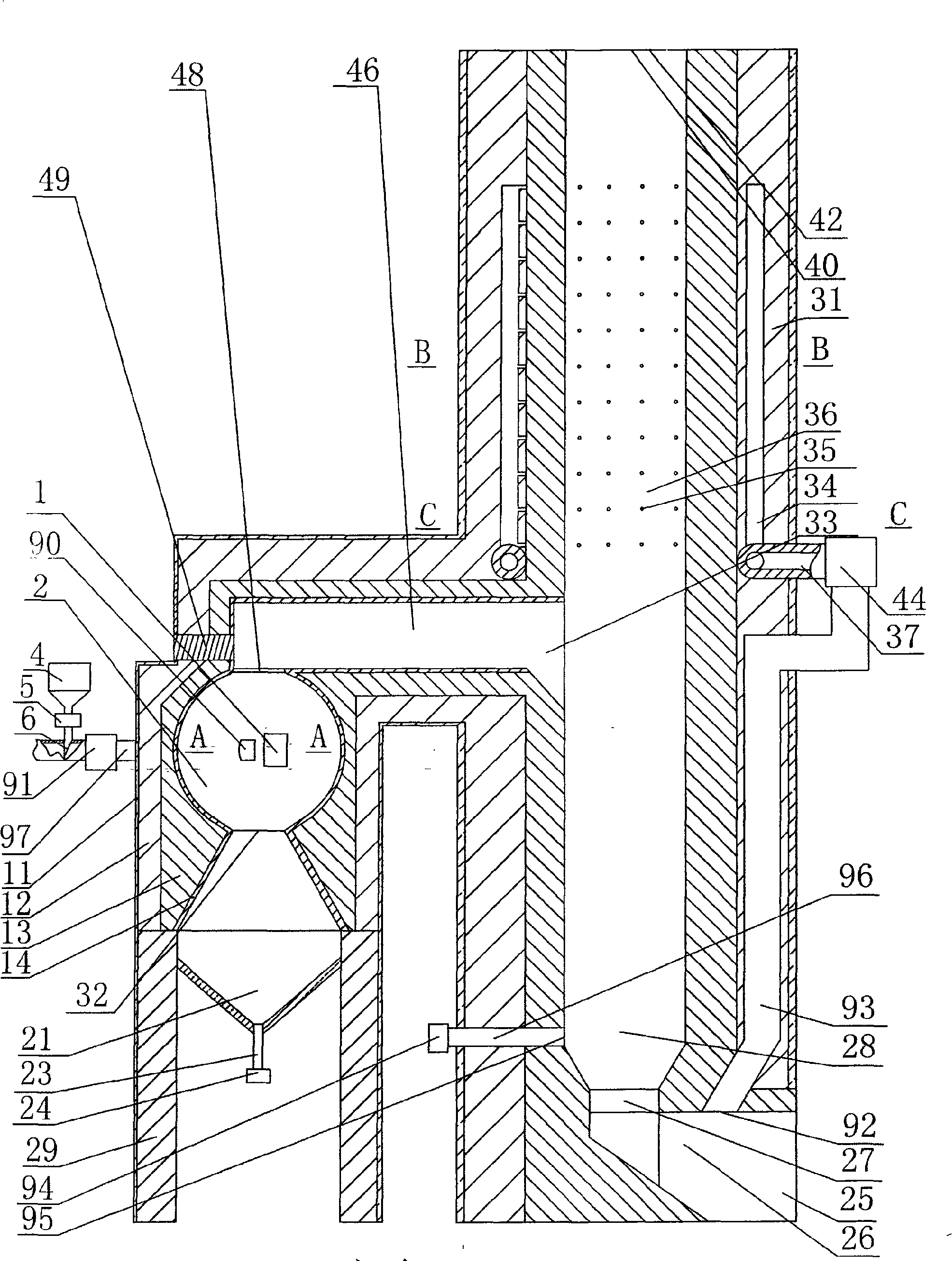
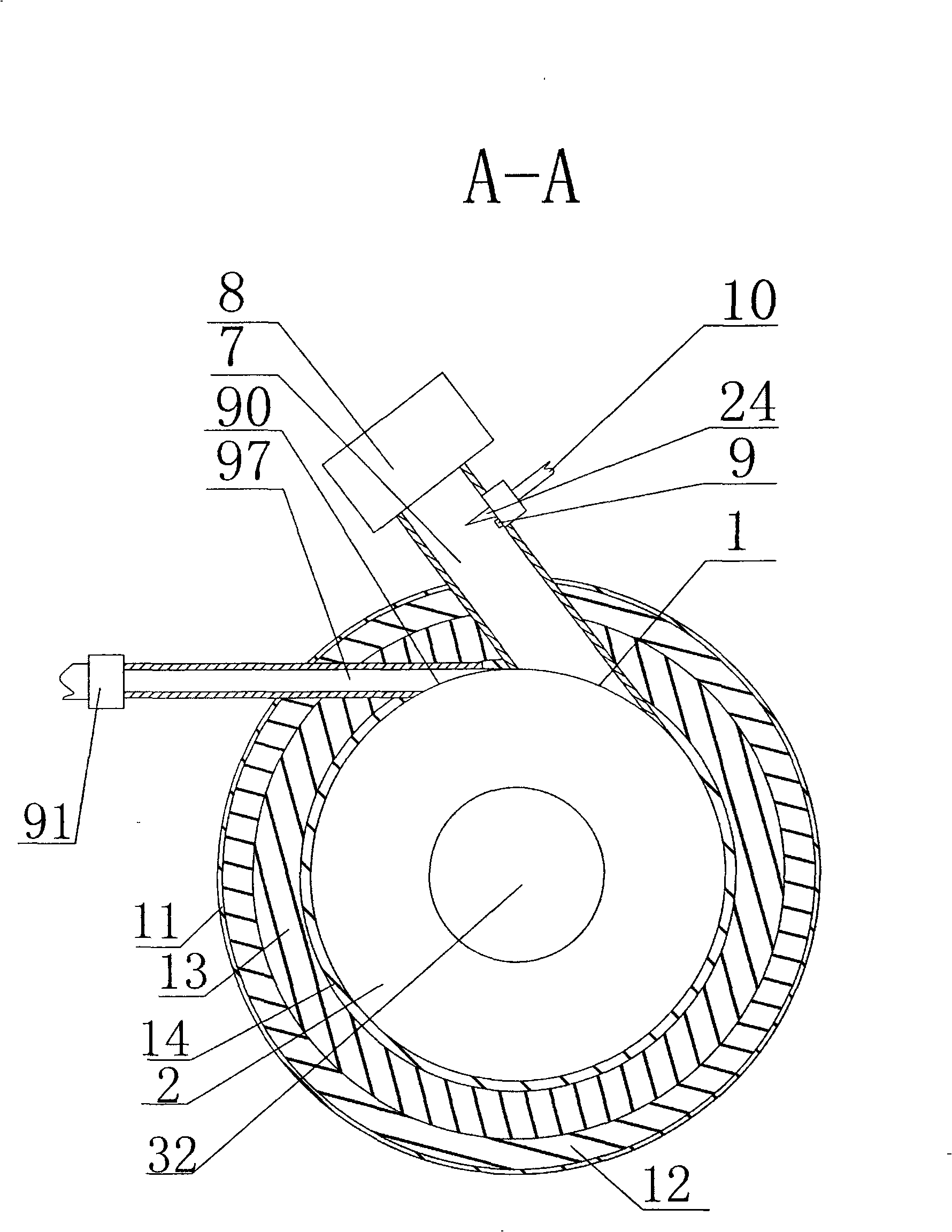
[0007] The main structure of the present invention is: the vertical kiln includes: fuel supply device, combustion chamber, kiln chamber, fan, air pipe, refractory material, heat preservation material, the side wall of the combustion chamber 2 is provided with an air inlet 1, and the air inlet 1 is connected to the air inlet pipe 7 , blower fan 8 is installed on the intake pipe 7, and the combustion chamber is connected to the fuel supply device, and the blower fan 8 can make the airflow rush into the combustion chamber by the blower fan 8 to pressurize the airflow, so that the airflow forms a vortex in which the rotation axis is perpendicular to the ground in the combustion chamber. The fuel supply device can be directly connected to the combustion chamber through the fuel pipe. When liquid or gaseous fuel is used, the fuel supply device can directly deliver the pressurized liquid or gaseous fuel into the combustion chamber through the fuel pipe. When solid fuel is used, the fu...


PUM


Abstract

A shaft kiln is more energy-saving and environment-friendly through utilizing hot convection and vortex burning in the novel burning method and heating method. The shaft kiln can form eddying turbulence in a kiln chamber through utilizing pressurized air flow, and makes the material have even heating. As the movement is mutual, the heating method of rolling material is replaced by the movement of hot air flow around the material, and the material naturally moves to a preheating zone, a heating zone and a cooling zone through utilizing the natural settling, and the shaft kiln is provided with a fuel supply device, a burning chamber, a kiln chamber, a fan, an air pipe, refractory material and heat-insulating material. The shaft kiln is characterized in that an air inlet is arranged on the side walls of the burning chamber, and is connected with an air inlet pipe, and the fan is installed on the air inlet pipe, the burning chamber is connected with the fuel supply device, the kiln chamber is provided with a heating chamber and a cooling chamber, the lower portion of the heating chamber is communicated with the cooling chamber, a feeding inlet is arranged on the upper portion of the heating chamber, and an air outlet is arranged on the upper portion of the heating chamber, a discharge port is arranged on the lower portion of the cooling chamber, a kiln chamber air inlet is arranged between the heating chamber and the cooling chamber, and the burning chamber is provided with an air outlet which is communicated with a kiln air inlet.

Description

technical field [0001] The invention relates to the field of kiln equipment, in particular to a shaft kiln. Background technique [0002] Existing shaft kilns are mostly used for producing cement, lime, roasting, and calcining various ores and massive materials, etc., which generally have high energy consumption, insufficient environmental protection emissions, low heat utilization rate, mixed coal combustion in the kiln, and poor fuel combustion. Sufficient, too much dust and harmful gas emissions, uneven temperature in the furnace, unable to burn powdery materials and other problems. Contents of the invention [0003] The purpose of the present invention is to provide a shaft kiln with a new structure, which can make the fuel burn more fully, the energy utilization rate is higher, the emission is more environmentally friendly, and the harmful gas emission is greatly reduced, which can make the product more excellent, save energy and reduce consumption, and reduce product...

Claims


Application Information

Patent Timeline
IPC IPC(8): F27B1/00F27B1/10F23C3/00F23C7/00
Inventor 陈久斌
Owner 陈久斌
Why Eureka
Try Eureka