Diamond thin wall drill tool-tip sintering forming die

A diamond and cutter head technology, which is applied in the field of hot-pressing sintering molding molds for diamond thin-walled drill bits, can solve the problems of wasting precious metal materials, difficult disassembly and assembly of molds, and low production efficiency, so as to reduce production costs and improve production efficiency , the effect of prolonging the service life

Inactive Publication Date: 2009-02-04
泉州众志金刚石工具有限公司
View PDF0 Cites 6 Cited by
  • Summary
  • Abstract
  • Description
  • Claims
  • Application Information

AI Technical Summary

Problems solved by technology

[0003] The purpose of the present invention is to solve the technical problems of low production efficiency, waste of precious metal materials, difficult disassembly and easy damage of the existing diamond thin-walled drill bits, and to provide a sintering molding mold capable of forming diamond thin-walled drill bits at one time. , the open water tank on the cutter head can be directly sintered to avoid defects such as ink and corner drop in the pressed cutter head, and fully guarantee the appearance and quality of the diamond thin-walled drill bit; the mold is easy to disassemble and assemble, greatly extending the service life of the mold Long, improve production efficiency, minimize the production cost of the cutter head

Method used


Image

  • Diamond thin wall drill tool-tip sintering forming die
  • Diamond thin wall drill tool-tip sintering forming die
  • Diamond thin wall drill tool-tip sintering forming die

Examples


Embodiment Construction

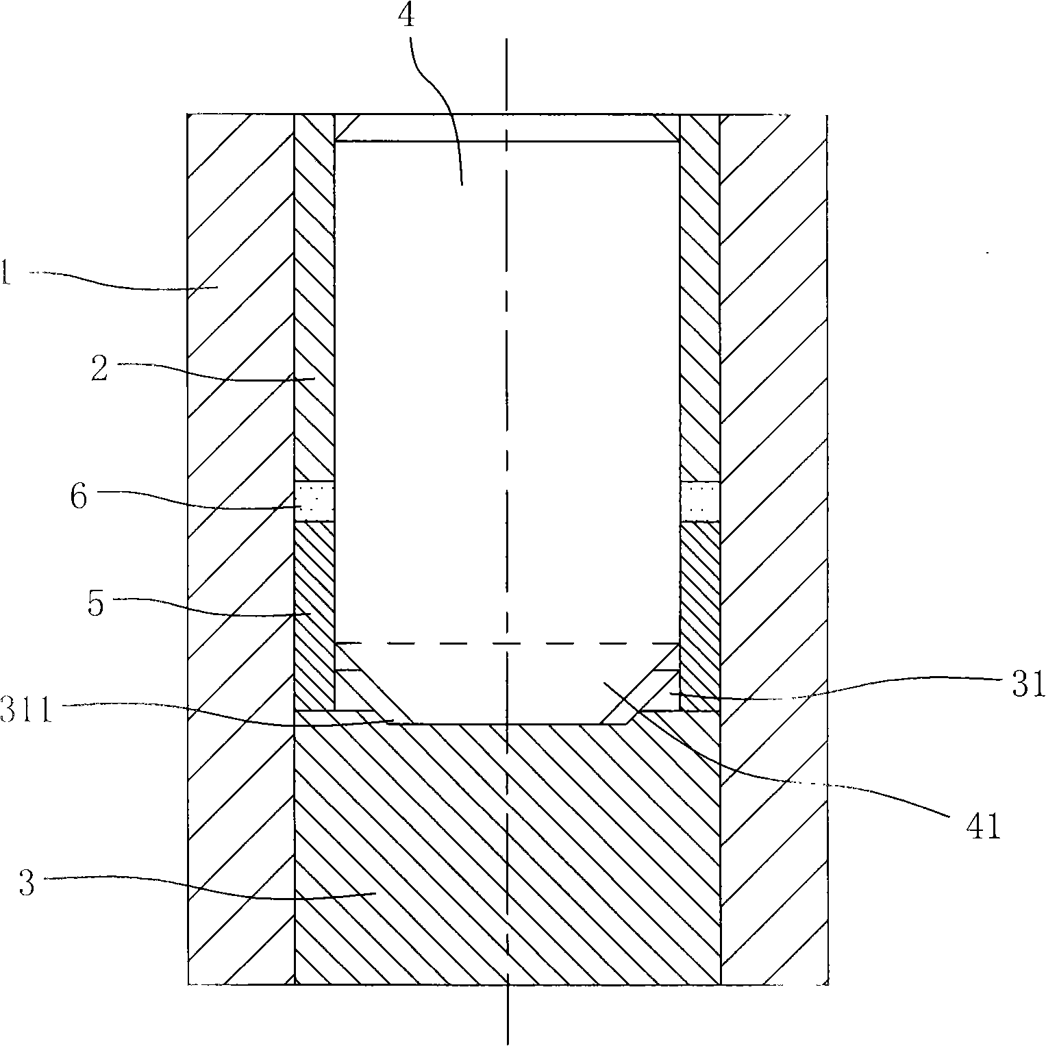
[0019] Such as image 3 , Figure 4 shown. The sintering forming mold of the diamond thin-walled drill head includes a die 1, upper and lower pressing heads 2, 3, a mold core 4 and an insert 5 for forming a water tank of the cutter head.

[0020] Such as image 3 , Figure 4 shown. The die 1 has a central hole that runs through up and down, and the inner diameter of the central hole is equal to the outer diameter of the diamond thin-walled drill bit to be made. from Figure 4 It can be seen from the figure that in order to facilitate easy mold removal and avoid damage to the mold, the die 1 is made into a separate structure, and is formed by closing the left and right symmetrical half dies a and b through the mold clamping mechanism.

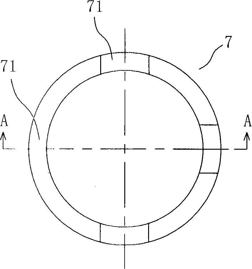
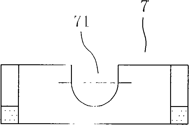
[0021] Such as image 3 , Figure 5 , Image 6 shown. The lower pressing head 3 fits in the center hole of the die and can move up and down along the center hole; the middle part of the top surface of the lower pressing head 3 is reces...


PUM


Abstract

The invention discloses a mould for sintering a cutter head of a thin-wall diamond bit. The die comprises a concave die with an up-and-down communicated center hole, of which the inside diameter is equal to the external diameter of the cutter head, a lower pressure head which can be movably matched in the center hole of the concave die in an up-and-down way, a mould core which is sheathed in the center hole of the concave die arranged above the lower pressure head and of which the external diameter is equal to the inside diameter of the cutter head, a center concave hole which is not communicated and arranged on the middle part of the top surface of the lower pressure head and of which the size is equal to the external diameter of the mould core, wherein, the lower end part of the mould core is inserted in the central hole of the lower pressure head and is supported on the low pressure head; a moulding cavity is formed between the mould core and the concave mould. The die also comprises a plurality of arc-shaped plate molding inserting blocks, of which the thickness is equal to that of the moulding cavity, scarf joints which are equidistantly arranged on the top surface of the lower pressure head, wherein, each scarf joint is embedded with the moulding inserting block, the lower part of the moulding inserting block is embedded into the middle part and the upper part of the scarf joint and then extends into a moulding cutter head water tank of the moulding cavity. The mould realizes one-step sintering and moulding of the cutter head of the thin-wall diamond bit and the open water tank on the cutter head can be sintered directly. Therefore, the mould has long service life and convenient disassembly and assembly.

Description

technical field [0001] The invention relates to a hot-pressing sintering mold for diamond products, in particular to a hot-pressing sintering forming mold for diamond thin-walled drill bits. Background technique [0002] Thin-walled drill bits are widely used in drilling processing in stone processing, engineering construction, geological exploration and other fields. The diamond cutter head of the drilling part is welded by high frequency. from figure 1 with figure 2 It can be seen from the figure that there are water grooves 71 of different sizes on the end surface of the diamond cutter head 7 for this kind of thin-walled drill bit, and the water grooves 71 can play the role of removing chips and improving the sharpness. In the past, most of the drill bits were welded along the diameter of the drill base in the form of segments, and the gaps between the segments were used as water tanks. The welding efficiency of the block form is low, the neutrality is poor, and the w...

Claims


Application Information

Patent Timeline
Patent Type & Authority Applications(China)
IPC IPC(8): B22F3/12B22F5/00B23P5/00E21B10/46
Inventor 石金龙许晓旺
Owner 泉州众志金刚石工具有限公司
Why Eureka
Try Eureka