Liquid gas injection system

一种液体、液体源的技术,应用在混合机、水/污泥/污水处理、生物水/污水处理等方向,能够解决环境污染、鼓风机消耗大能源等问题,达到提高溶解度、节约成本、提高效率的效果

Active Publication Date: 2009-02-04
白冬生
View PDF0 Cites 5 Cited by
  • Summary
  • Abstract
  • Description
  • Claims
  • Application Information

AI Technical Summary

Problems solved by technology

For the widely used sewage biological treatment project, the blower used will consume a lot of energy, such as electricity, and will also cause environmental pollution

Method used


Image

  • Liquid gas injection system
  • Liquid gas injection system
  • Liquid gas injection system

Examples


Embodiment Construction

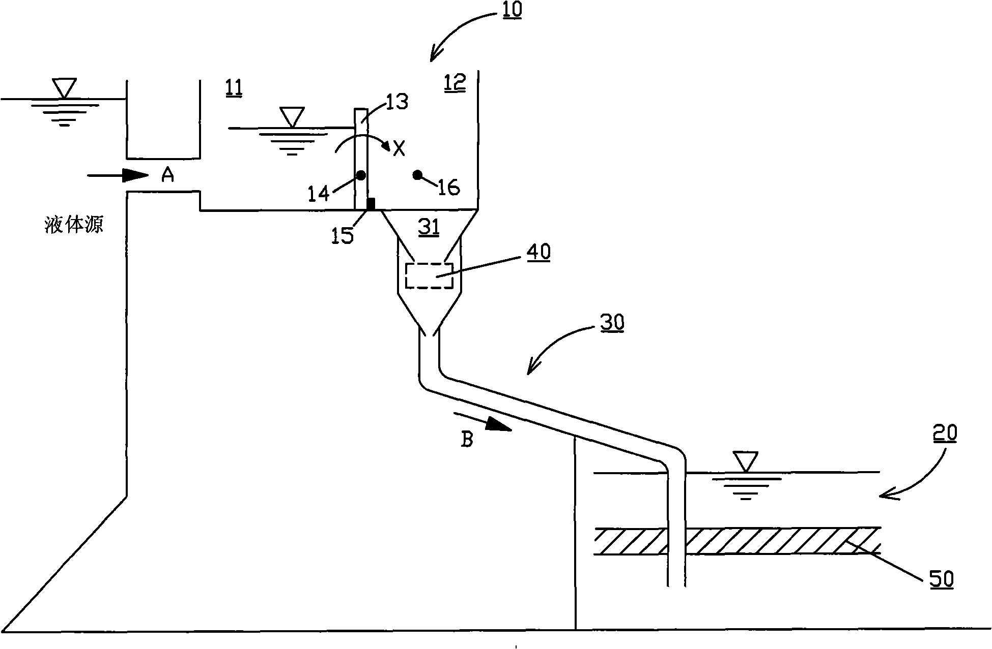
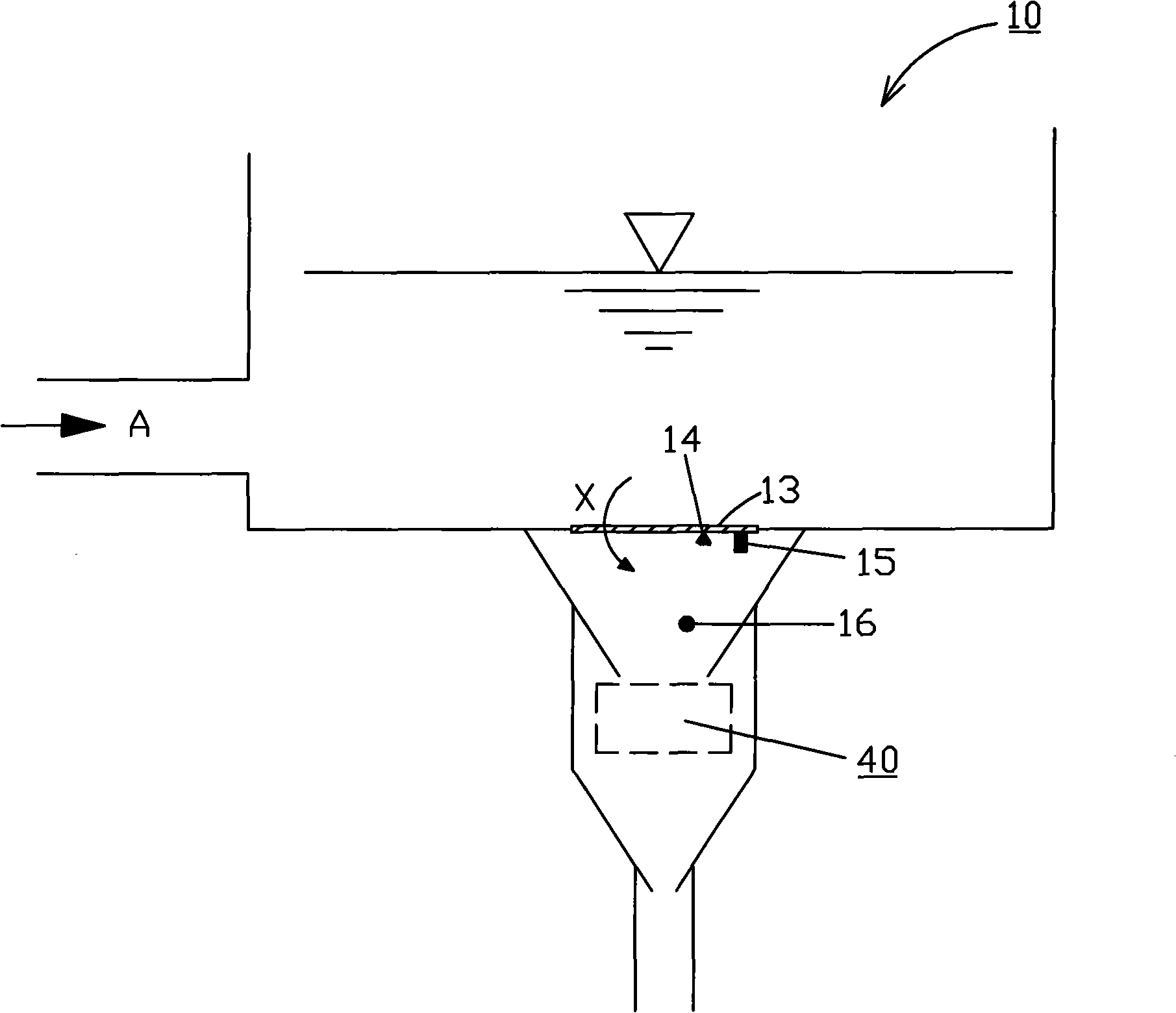
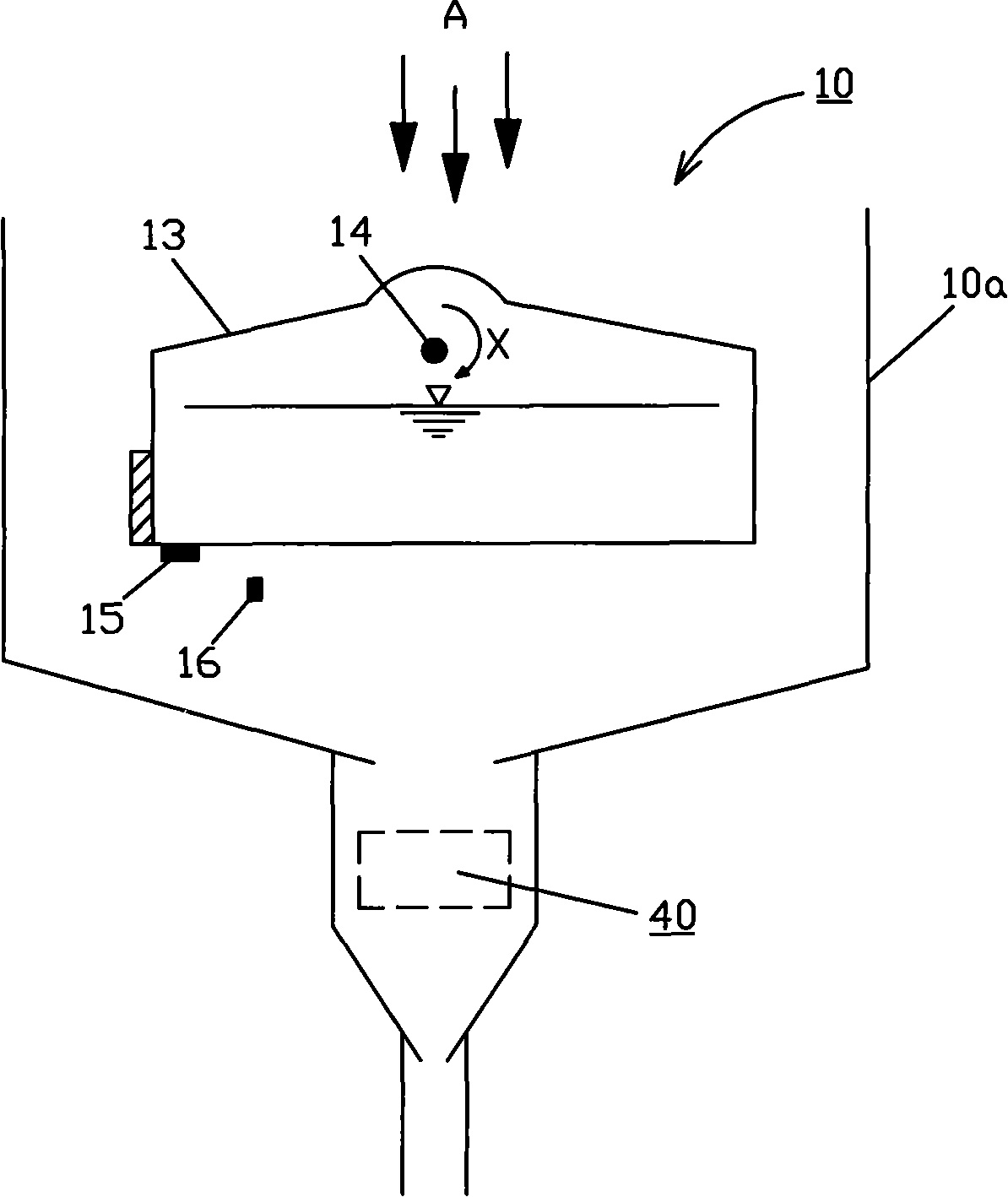
[0017] Such as figure 1 As shown, according to a typical embodiment of the present invention, a liquid gas injection system is provided, which mainly includes: an upstream intermittent liquid supply device 10 for receiving liquid from a liquid source; a downstream liquid storage A device 20 for intermittently and quantitatively receiving liquid from the intermittent liquid supply device 10; and a pipeline 30 connected between the upstream intermittent liquid supply device 10 and the downstream liquid storage device 20, the outlet of the pipeline 30 is located Below the liquid level in the liquid device 20, the liquid in the upstream intermittent liquid supply device 10 is intermittently and quantitatively flowed into the downstream liquid storage device 20 through the pipeline 30 by utilizing the liquid level difference between the upstream and downstream, and at the same time The gas in the pipeline 30 is injected into the liquid in the liquid storage device 20 .

[0018] In...


PUM


Abstract

The invention provides a liquid gas injection system which comprises: an upstream intermittent liquid supply device for receiving liquid from a liquid source; a downstream liquid storage device for intermittently and quantitatively receiving the liquid from the intermittent liquid supply device; and a pipeline which is connected between the upstream intermittent liquid supply device and the downstream liquid storage device, an outlet of the pipeline is positioned below liquid surface in the liquid storage device, thereby leading the liquid in the upstream intermittent liquid supply device to utilize the liquid level difference between the upstream and the downstream devices to be intermittently and quantitatively flowed into the downstream liquid storage device through the pipeline, and gas in the pipeline is simultaneously injected into the liquid in the liquid storage device. The gas injection system of the invention utilizes the liquid level difference which is generally existed in nature to automatically inject the gas into the liquid, the gas injection system does not need to use a blower and other gas injection devices, so the liquid gas injection system can not consume energy or pollute the environment; furthermore, the liquid gas injection system can greatly save the cost.

Description

technical field [0001] The invention relates to a system for injecting gas into a liquid. Background technique [0002] In the prior art, it is often necessary to inject gas into the liquid. [0003] For example, in the biological treatment project of sewage (such as industrial sewage or domestic sewage), it is necessary to inject air into the sewage to provide sufficient oxygen for the aerobic microorganisms in the sewage. The microorganism decomposes the organic pollutants in the sewage into simple inorganic substances such as carbon dioxide, water, sulfate, and nitrate through the processes of condensation, adsorption, oxidation, and decomposition, and converts toxic and harmful substances into non-toxic and harmless substances. Sewage is purified. [0004] In the aquaculture industry, if the dissolved oxygen in the water is lower than 4 mg / L, it will be difficult for fish to survive, so it is necessary to supply oxygen to the water to provide the fish in the water with...

Claims


Application Information

Patent Timeline
Patent Type & Authority Applications(China)
IPC IPC(8): C02F3/12
CPCB01F3/04496B01F15/0218C02F3/22Y02W10/37Y02W10/10B01F23/2322B01F35/71411
Inventor 盛国华
Owner 白冬生
Why Eureka
Try Eureka