
Permanent magnet wind power generator of combined stator structure

A technology for wind turbines and combined stators, which is applied to the shape/style/structure of the magnetic circuit, and the static parts of the magnetic circuit, etc., can solve the problem of the large span of the integer slot winding stator, the difficulty of embedding the motor winding, and the reduction of starting resistance torque. and other problems, to achieve the effect of convenient wire embedding, small air gap and reducing starting resistance torque

Inactive Publication Date: 2009-02-04
SHENYANG POLYTECHNIC UNIV
View PDF0 Cites 4 Cited by
  • Summary
  • Abstract
  • Description
  • Claims
  • Application Information

AI Technical Summary

Problems solved by technology

However, the choice of closed slots for permanent magnet motors brings great difficulties to the embedding of the motor windings, and it is difficult to adopt in actual motor production. The stator of the current permanent magnet wind turbine is not much different from that of ordinary motors, so it is urgent to propose a New structure to reduce starting drag torque
[0003] Generally, the pole-slot ratio of the motor is far less than 1. Due to the large number of poles of the direct-drive permanent magnet generator, if the integer-slot winding stator span is large, the problem is that the end is longer, wasting materials and causing losses. As well as problems such as heat at the end, the above reasons lead to poor results when applied to low-speed direct-drive permanent magnet wind turbines, so a new pole slot fit is proposed

Method used


Image

  • Permanent magnet wind power generator of combined stator structure
  • Permanent magnet wind power generator of combined stator structure
  • Permanent magnet wind power generator of combined stator structure

Examples


Embodiment Construction

[0013] The detailed structure of the present invention is described in conjunction with the following examples and accompanying drawings.

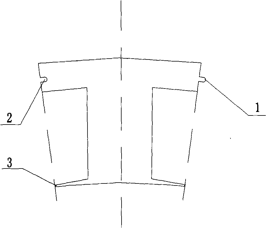
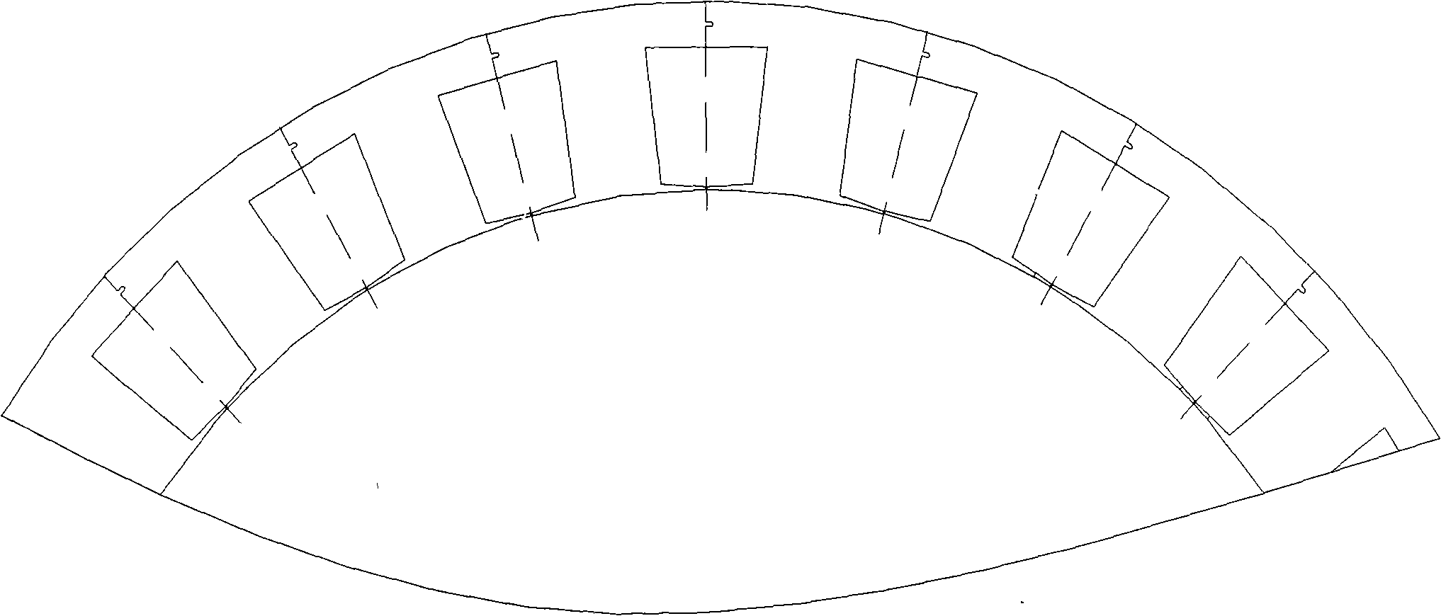
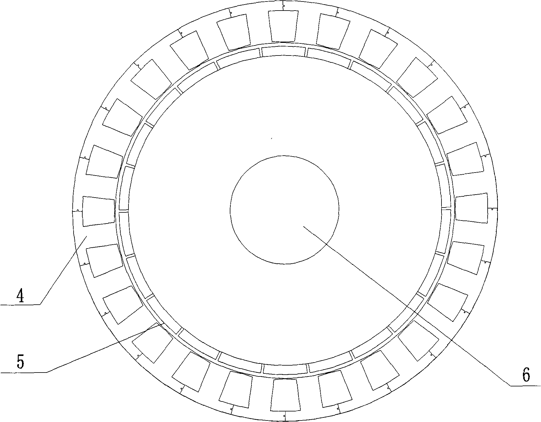
[0014] As shown in the figure, the permanent magnet wind generator includes a stator 4, a rotor 5, a bearing, an end cover and a shaft, wherein the stator 4 is in the shape of a hollow cylinder, and the hollow cylinder is formed by splicing magnetic poles, coils are wound on the magnetic poles, and the magnetic poles are It is formed by stacking punches, the punches are in the shape of "I", the upper and lower edges are arc-shaped, and there are a punching protrusion 1 and a punching groove 2 on both sides of the punching yoke, and the punchings are stacked At the same time as the magnetic pole is formed, the punching protrusion 1 and the punching groove 2 are laminated to form a magnetic pole protrusion and a magnetic pole groove respectively, and two adjacent magnetic poles are joined together by the magnetic pole protrusion and the magne...


PUM


Abstract

The invention provides a permanent magnet wind motor with a combinatorial stator structure which belongs to permanent magnet wind motor field, adopting the technical proposal that: I-shaped punching sheets are laminated to form magnetic poles, a punching sheet bulge and a punching sheet groove are arranged at both sides of a yoke part of the punching sheet, the punching sheet bulge and the punching sheet groove are laminated respectively to form a magnetic pole bulge and a magnetic pole groove when the punching sheets are laminated as magnetic poles, coils are reeled around the magnetic poles to form stator windings, two adjacent magnetic poles are jointed and fixedly welded through the magnetic bulges and the magnetic grooves, the magnetic poles joint a hollow cylinder-shaped stator around the circumference, the pole groove ratio of the stator and the rotor is 24 : 22 or 24n : 22n, n is a natural number, the rotor is embedded in the central part of the stator, an axis is inserted into a wheel hub of the rotor, the axis is in connection with a bearing cone, a bearing cup is in connection with an end cover, the bearing drives the axis to roll and accordingly the axis drives the rotor to roll.

Description

technical field [0001] The invention relates to the technical field of generators, in particular to a permanent magnet wind generator with a combined stator structure. Background technique [0002] The national standard GB / T10760.1-2003 has regulations on the limit value of the starting resistance torque value of the off-grid permanent magnet wind turbine under no-load conditions. From the actual application situation, the starting resistance torque of the permanent magnet wind turbine is smaller. The better it is, the smaller the starting resistance torque can make the permanent magnet wind generator start and generate electricity under the breeze, which improves the utilization rate of wind energy. The starting resistance torque of the permanent magnet wind turbine mainly includes: friction, hysteresis torque and cogging torque; in order to reduce the starting resistance torque, we mainly start from these three aspects, in which the cogging torque occupies the vast majorit...

Claims


Application Information

Patent Timeline
Patent Type & Authority Applications(China)
IPC IPC(8): H02K1/12H02K1/16H02K1/14
Inventor 唐任远安忠良毕海涛刘万振
Owner SHENYANG POLYTECHNIC UNIV
Learn More