Oil-gas separating device for engine

An oil and gas separator and engine technology, which is applied to engine components, machines/engines, mechanical equipment, etc., can solve the problems of large resistance, large filter element resistance, and high separation efficiency, and achieves reduced resistance, better oil and gas separation effect, and reduced system The effect of resistance

Active Publication Date: 2009-02-11
CHERY AUTOMOBILE CO LTD
View PDF0 Cites 8 Cited by
  • Summary
  • Abstract
  • Description
  • Claims
  • Application Information

AI Technical Summary

Problems solved by technology

[0003] These two oil-gas separators are characterized by low resistance and maintenance-free, but the disadvantage is low separation efficiency. There are also a small number of engines that use filter-type oil-gas separators,

Method used


Image

  • Oil-gas separating device for engine

Examples


Embodiment Construction

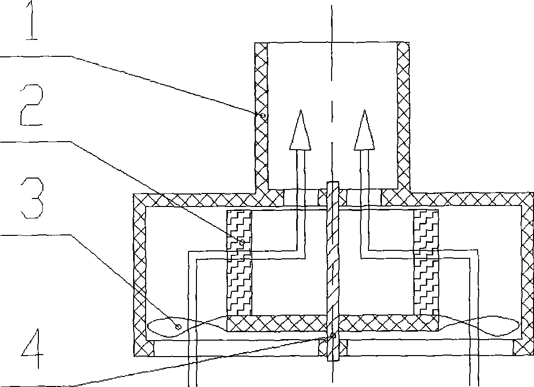
[0010] As shown in the figure, the engine oil-gas separator has a casing 1 , blades 3 , a filter element 2 , and a rotating shaft 4 , wherein the blades 3 and the filter element 2 are fixed on the rotating shaft 4 , and the rotating shaft is mounted on the casing 1 .

[0011] The blade 3, the filter element 2 and the rotating shaft 4 are all rigidly connected, and the filter element is located above the blade. The housing 1 is provided with a mounting hole for the rotating shaft. The housing can be arranged on the valve cover, the timing cover or the crankcase, or can be integrated with the valve cover, the timing cover or the crankcase to make the engine structure more compact.

[0012] The arrows in the figure show the flow direction of the crankcase gas. The crankcase gas first passes through the blades 3 to drive the filter element 2 to rotate around the rotating shaft 4. At the same time, the crankcase gas flows radially, resulting in cyclone separation, which can separa...


PUM


Abstract

The invention relates to a gas-oil separator of an engine with high gas-oil separating efficiency and low resistance. The technical proposal is as follows: the gas-oil separator of the engine is characterized in that vanes, a filter element and a rotation shaft are arranged, wherein, the vanes and the filter element are fixed on the rotation shaft which is arranged on a shell. The gas-oil separator combines the structural features of a filter element type gas-oil separator and a cyclone type gas-oil separator, the gas from a crank case is separated by the vanes for the first time and by the filter element once again, meanwhile, as the filter element can rotate, oil drops attached to the filter element can be separated from the filter element under the action of centrifugal force, thus effectively reducing the resistance of the filter element, achieving the optimal gas-oil separating effect and lowering the resistance of the system.

Description

technical field [0001] The invention relates to an engine crankcase ventilation system, in particular to an engine oil-gas separator. Background technique [0002] Most of the existing engine crankcase ventilation systems use labyrinth or cyclone oil and gas separators. The way to realize the oil and gas separation of the labyrinth type oil and gas separator is: when the oil and gas mixture passes through the labyrinth, due to inertia, the small oil droplets in the mixture will hit the wall of the labyrinth and flow down along the wall, and the gas in the mixture will go smoothly. Enter the crankcase ventilation system through the labyrinth. The separation method of the cyclone oil and gas separator is similar to that of the labyrinth oil and gas separator, except that the small oil droplets in the mixture hit the wall of the oil and gas separator under the action of centrifugal force and flow down along the wall. [0003] These two kinds of oil and gas separators are char...

Claims


Application Information

Patent Timeline
IPC IPC(8): F01M13/04
Inventor 高建鹏
Owner CHERY AUTOMOBILE CO LTD
Why Eureka
Try Eureka