Intelligence control tunnel LED illuminating system and use thereof

A lighting system, intelligent control technology, applied in general control systems, control/regulation systems, outdoor lighting, etc., can solve the problems of insufficiency, waste of electric energy, more than 10 minutes, and the fastest 5 minutes, etc. The effect of prolonging the working life

Active Publication Date: 2009-02-11
SHANGHAI SANSI ELECTRONICS ENG +2
View PDF0 Cites 30 Cited by
  • Summary
  • Abstract
  • Description
  • Claims
  • Application Information

AI Technical Summary

Problems solved by technology

At present, LED tunnel lights have products on the market, but their main disadvantage is that they do not have intelligent control functions like traditional tunnel lighting fixtures such as high-pressure sodium lamps.
[0004] In actual use, no matter whether there are people or vehicles passing through the tunnel, the existing LED tunnel lights are always on. This is not inappropriate for urban tunnels with heavy traffic, but it is not suitable for tunnels in remote areas where the traffic is clearly divided into busy and idle, or at night. The irrationality of a tunnel with a small traffic flow immediately stands out
When there is no car passing through the tunnel for a long time, the long-on state of the tunnel lights will inevitably cause a serious waste of electric energy
Traditional high-pressure sodium lamps and other tunnel lighting fixtures have no good measures to improve this, because it usually takes more than 10 minutes to form a normal illumination every time it is turned on, and it takes 5 minutes at the fastest, which cannot meet the requirements of "turning off when there is no car, and turning off when there is a car". Instant light" intelligent control requirements

Method used


Image

  • Intelligence control tunnel LED illuminating system and use thereof

Examples


Embodiment Construction

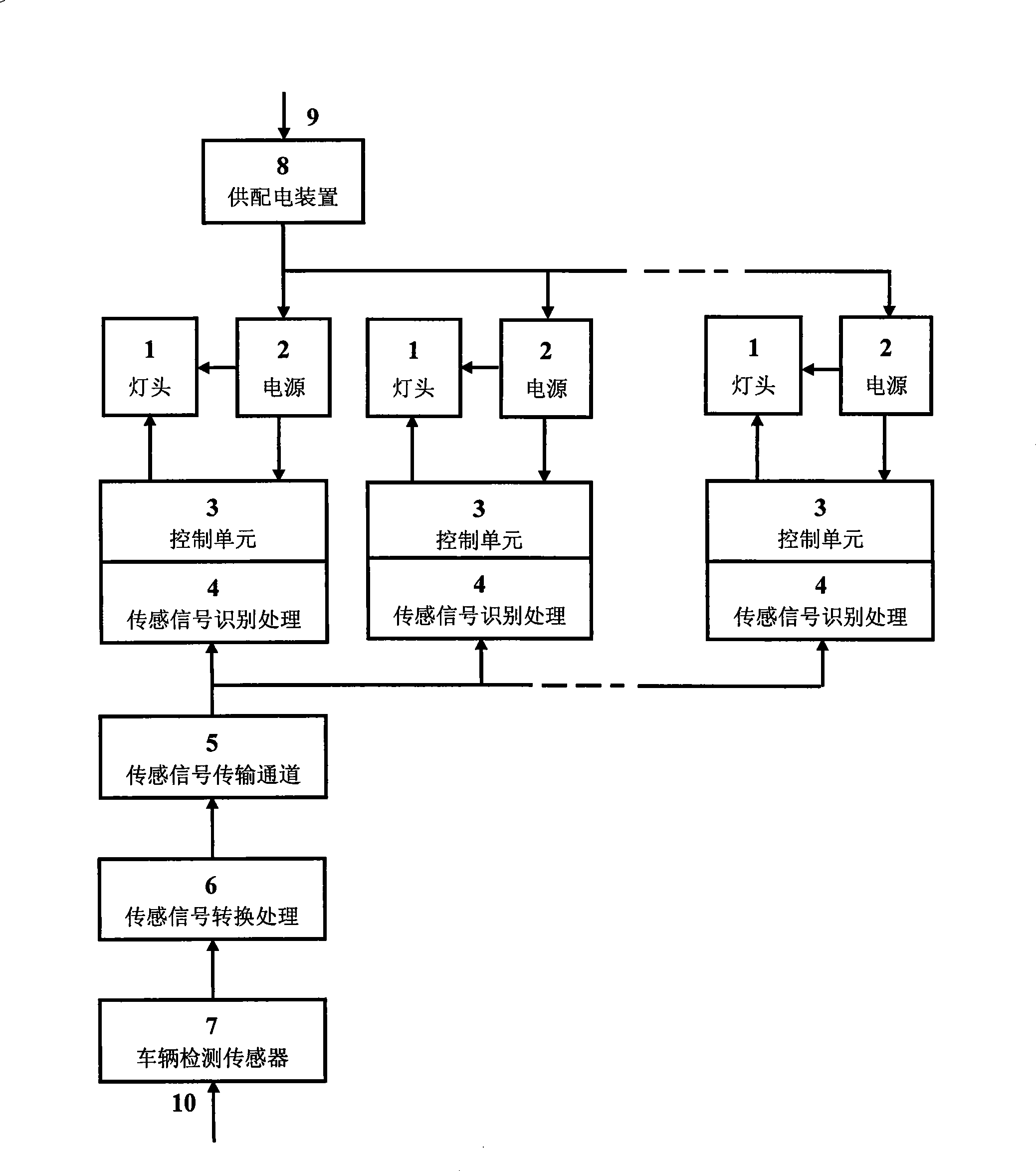
[0014] The following is attached with the manual figure 1 The LED tunnel light lighting system with intelligent control function using infrared detection as vehicle detection sensor is further described for the present invention:

[0015] figure 1 A group of multiple LED tunnel lights is composed of a tunnel light base 1 , a DC drive power supply 2 and a control unit 3 . The power supply and distribution device 8 is connected to the power supply from the power supply inlet 9, and supplies power to the built-in DC driving power supply 2 of each LED tunnel light respectively, and the output of the DC driving working power supply provides two DC outputs, one of which is used as the LED tunnel light lamp holder 1 The driving power of the other way is used as the line working power of the control unit 3. In the present invention, a sensing signal identification processor 4 with a temperature sensor is provided in the control unit 3 of each LED tunnel light. The front ends of the...


PUM


Abstract

The invention discloses an illumination system of an intelligent controlled LED tunnel lamp and the application thereof, which comprises a power supply and distribution device, a group of structure including a plurality of LED tunnel lamps that consist of tunnel lamp burners, direct current drive working power and control units. A sensing signal recognition processor added with a temperature sensor is arranged in each control unit of the LED tunnel lamps in the invention; the front end of the sensing signal recognition processor is successively connected with a sensor signal converting processor and a vehicle detecting sensor through a preposed sensing signal transmission channel in a many-to-one way; signals from the temperature sensor and the vehicle detecting sensor are treated uniformly by the sensing signal recognition processor. The invention can recognize whether vehicles comes from the front of the tunnel so as to control whether the LED tunnel lamps are lightened, and the driving current of the LED tunnel lamp caps or the lightened number of the LED tunnel lamps can be adjusted and controlled according to the detected environment temperature in the tunnel without reducing the brightness of the tunnel lamps, thus realizing the power saving and prolonging the working life of the tunnel lamps.

Description

technical field [0001] The invention relates to a lighting system for a tunnel and its application, in particular to a tunnel lighting system and its application which use LEDs as light sources and whose on-off state and power consumption can be controlled. Background technique [0002] Tunnel lighting belongs to engineering lighting with large illumination area and high illumination requirements. Commonly used tunnel lighting lamps are high-pressure sodium lamps, high-pressure mercury lamps and halogen lamps. It consumes a lot of power and has a short lifespan. Not only does it take a long time to start (10-15 minutes), it is not easy to start at low temperature, but it is also difficult to meet the requirements of environmental protection because it contains harmful substances such as mercury. [0003] With the advancement of LED technology, LED tunnel lights are increasingly becoming an ideal new tunnel lighting device. It uses LED as the light source, which has the adv...

Claims


Application Information

Patent Timeline
Patent Type & Authority Applications(China)
IPC IPC(8): F21S2/00H05B37/02G05B13/02F21S8/00F21W131/101F21Y101/02F21K9/00F21Y115/10
Inventor 王鹰华汪梦生成鑫
Owner SHANGHAI SANSI ELECTRONICS ENG
Why Eureka
Try Eureka