Wideband dual-linear polarization bipole antenna array

A dipole antenna, dual linear polarization technology, applied in antenna element combinations with different polarization directions, resonant antennas, mid-position feed between antenna endpoints, etc. Due to the problems of complexity and the unavailability of the dipole unit form, the effects of good unit applicability, small mutual coupling, and good polarization isolation performance are achieved.

Active Publication Date: 2009-02-11
CHINA ELECTRONIC TECH GRP CORP NO 38 RES INST
View PDF1 Cites 24 Cited by
  • Summary
  • Abstract
  • Description
  • Claims
  • Application Information

AI Technical Summary

Problems solved by technology

For the former arrangement of antenna elements orthogonal to each other, the structural form of the unit will be strictly limited, and many forms of dipole elements will not be applicable
For the latter, since each radiating element is composed of four dipole antenna elements, in order to achieve high isolation, each element is required to be fed in a balanced manner, which makes the design of the feeding network more complicated

Method used


Image

  • Wideband dual-linear polarization bipole antenna array
  • Wideband dual-linear polarization bipole antenna array
  • Wideband dual-linear polarization bipole antenna array

Examples


Embodiment 1

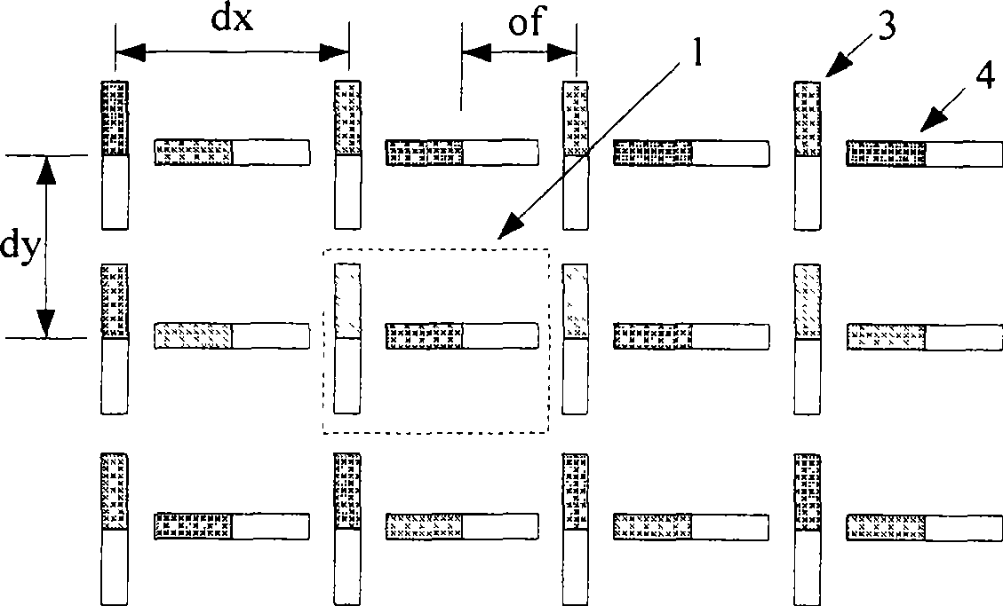
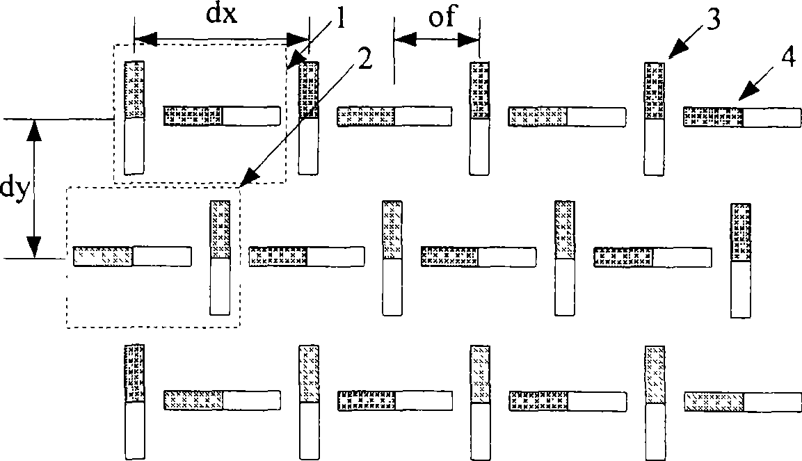
[0035] see figure 1 and figure 2 , each radiating element 1 in the figure is composed of a vertically polarized dipole antenna unit 3 and a horizontally polarized dipole antenna unit 4, which are arranged vertically in a "T" shape as shown in the figure, and each The distance between the centers of two polarized dipole antenna elements in a radiating element is half of the radiating element spacing in the corresponding direction, that is, of≈dx / 2. According to the positional relationship of the two polarization units to which each radiating element belongs in the array, the radiating elements can be arranged in a rectangular grid order (that is, the arrangement of the antenna elements in all radiating elements in the array is exactly the same), Such as figure 1; The reverse order arrangement of the triangular grid can also be adopted (that is, the antenna elements in the adjacent rows and columns of the array are arranged in a left-right or up-down reverse order), such as ...

Embodiment 2

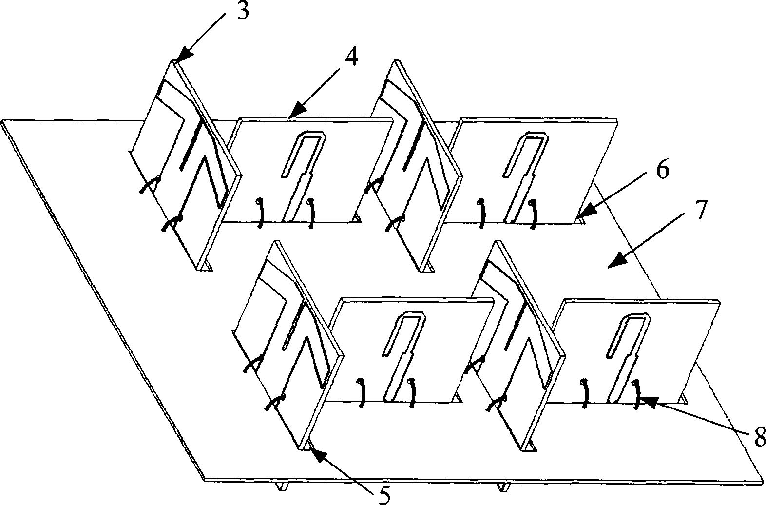
[0038] An L-band 3×8 unit dual-linearly polarized microstrip dipole antenna array, the structure diagram is as follows Figure 4 . The antenna array is composed of 24 radiating elements 1 , a conductor reflector 7 and three dual-polarization line feed networks 9 . Each radiating element is arranged in a rectangular grid order, in which there are 8 radiating elements in the row direction and 3 radiating elements in the column direction, and dx=0.62λ 0 ,dy=0.65λ 0 . Each radiating element is composed of a vertically polarized microstrip dipole antenna 3 and a horizontally polarized microstrip dipole antenna 4 arranged vertically in a "T" shape (the antenna unit used in the figure It is a well-known antenna unit in the art, and references can be seen: Brian Edward and Daniel Rees, A Broadband Printed Dipole with Integrated BALUN. MJ, 1987, 30 (5), PP339-344.). In order to facilitate the connection between each antenna unit and the line feed network, the conductor reflector 7 ...

Embodiment 3

[0043] A P-band 4×6 element dual-linearly polarized ultra-wideband antenna array, such as Figure 10 , the antenna unit is a microstrip Vivaldi antenna unit (reference: R. Janaswamy and D.H. Schaubert, Analysis of the tapered slot antenna, IEEE TAP., vol.35, pp.1058, Sept.1987.). In order to achieve the consistency of the phase centers of the two polarization states, each antenna unit adopts the following figure 2 The cell arrangement shown. Each antenna unit is directly fixed on the conductor reflection plate 7 by an L-shaped structural member 10 and fed by an N-shaped connector 11 . Take dx=0.5λ 0 ,dy=0.5λ 0 . The antenna array is simulated using the industry-recognized HFSS11.0 (high-frequency structure simulation software developed by Ansoft). Better than -25dB, port isolation better than 28dB.


PUM


Abstract

The invention relates to a broadband double-line polarization dipole antenna array used for receiving and transmitting a radio wave, which comprises at least two double-polarization dipole radiation elements, a conductor reflector plate and a feed system. The double-polarization dipole radiation element comprises two T-shaped dipole antenna units, one dipole antenna unit is vertically arranged in the middle of the other dipole antenna unit, and the polarization directions of antenna units are respectively parallel to two polarized states of the antenna array; the center distance between the two T-shaped dipole antenna units, one of which is vertically arranged in the middle of the other dipole antenna unit, is half the distance between radiation elements in the corresponding direction; the double-polarization dipole radiation element is the sequential arrangement array of a rectangular grid or the inverted sequence array of a triangle grid. The invention realizes a broadband double-line polarization antenna array which has the advantages of high isolation, low cross polarization, simple structure, and flexible and convenient feed, and at the same time has the engineering potential of realizing wide angle scan double-line polarization array.

Description

technical field [0001] The invention relates to a broadband dual-line polarized antenna for receiving and transmitting radio waves, in particular to a wide-band dual-line polarized antenna array. Background technique [0002] For the high-resolution SAR synthetic aperture radar system, in order to obtain the detailed information of different material characteristics of the imaging target, in addition to requiring the antenna to have a large working bandwidth, it is also required that the SAR has a multi-polarization (HH, VV, HV, VH) working mode , which requires the antenna to have broadband dual-line polarization capability. In terms of civilian use, the polarization diversity technology adopted by ground communication systems to resist multipath fading also promotes the development of dual-line polarized antenna technology. Therefore, the wideband dual-linearly polarized antenna technology is more and more widely used in military and civilian fields. [0003] At the same...

Claims


Application Information

Patent Timeline
Patent Type & Authority Applications(China)
IPC IPC(8): H01Q21/24H01Q9/16
Inventor 卢晓鹏彭海兵李雁张玉梅
Owner CHINA ELECTRONIC TECH GRP CORP NO 38 RES INST
Why Eureka
Try Eureka