Embolization device

A technology of embolization and positioning devices, applied in medical science, stents, dilators, etc., can solve problems such as fiber detachment and fiber danger

Inactive Publication Date: 2009-02-18
PFM医疗制品股份公司
View PDF9 Cites 13 Cited by
  • Summary
  • Abstract
  • Description
  • Claims
  • Application Information

AI Technical Summary

Problems solved by technology

[0009] Although the above-mentioned embolization devices are better suited for the occlusion of a hole located in the human or animal body than embolization devices without thrombus-forming

Method used


Image

  • Embolization device
  • Embolization device
  • Embolization device

Examples


Embodiment Construction

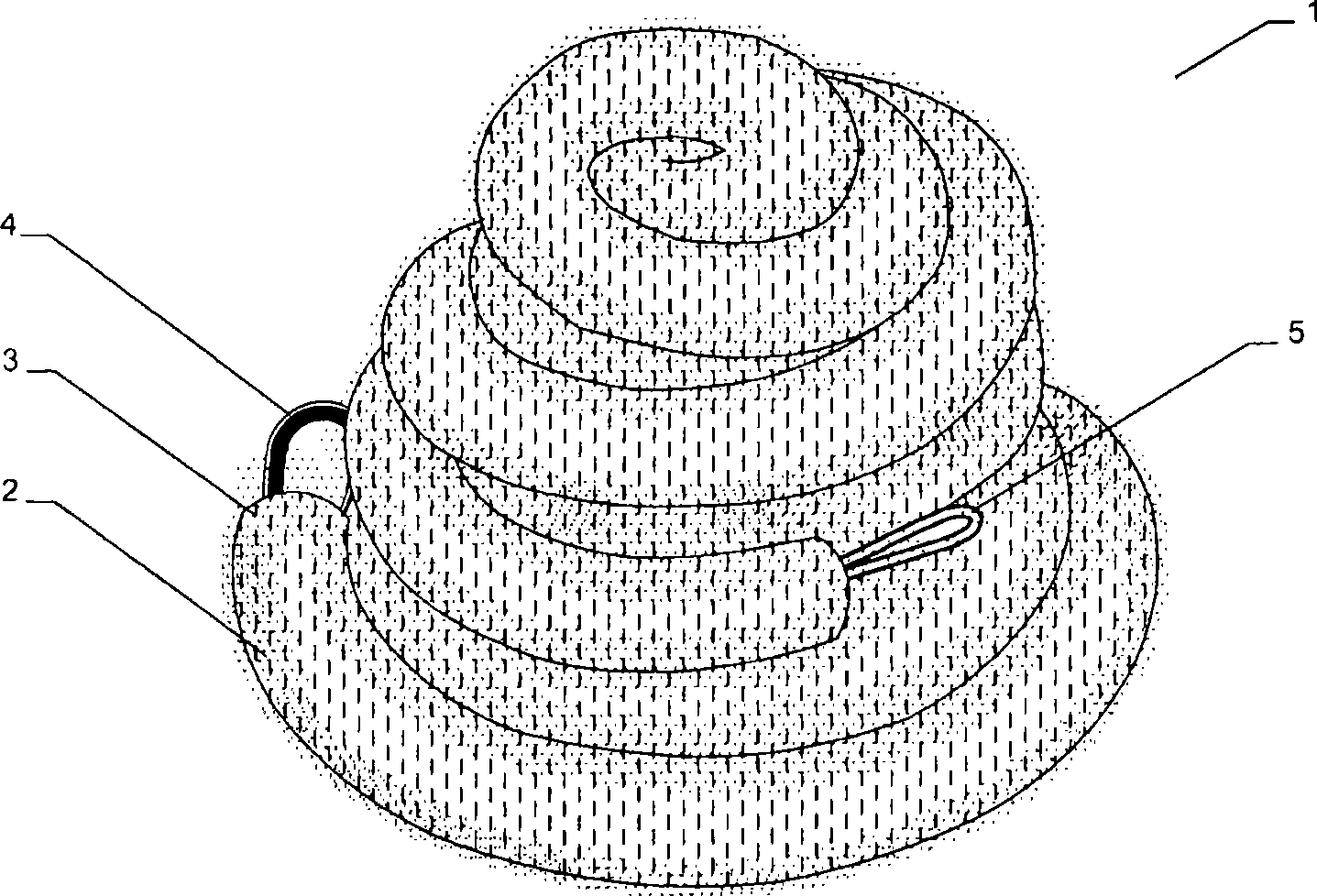
[0084] figure 1 A perspective view of a first embodiment of an embolization coil 1 is shown, which includes thrombus-forming fibers 2 . A plurality of thrombus-forming fibers 2 are wound around a base body 3 of the embolization coil 1 . The base body 3 has loops 4 , 5 on the end faces protruding from the wound parts, which are part of an inner needle guide, as will be explained further below. At least loop 5 is used to fix a positioning system, such as Figures 5 to 7 shown in . In this case, a retaining wire 6 of a positioning device 7 can engage in the loop 5 in order to be able to fix on the one hand and manipulate the plug screw on the other hand during the delivery process.

[0085] However, it is also possible to act on the plug screw with a further loop 4 arranged at one end of the plug screw, whereas the loop 5 is arranged on the outside of the plug screw in the region of its conically tapering portion.

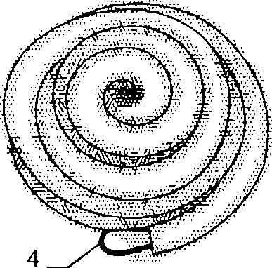
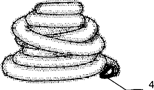
[0086] If specifically by Figures 2 to 4 According to the ...


PUM


Abstract

The invention relates to an embolization device (1) comprising a basal body (3) and at least one thrombogenic fibre (2) forming thrombus, wherein the basal body can be converted from an elongate primary shape to a secondary shape, the at least one thrombogenic fibre is arranged in a configuration wound around the basal body. In a method for producing an embolization coil of this kind, a primary coil (30) forming a basal body (3) of the embolization coil (1) has at least one thrombogenic fibre (2) wound around it, and the primary coil (30) is converted in shape to a secondary coil.

Description

technical field [0001] The present invention relates to a kind of embolization device (Embolisiereinrichtung), comprises a base body and at least one fiber that forms thrombus, wherein base body can be transformed into a secondary shape by a kind of elongated (langgestreckten) primary shape, also relates to a kind of method for producing such embolization device. Background technique [0002] A wide variety of shapes of occlusive devices are known. They are used for occlusion or partial occlusion of a blood vessel, organ passage or an other body orifice. An artificial occlusion can be produced by such an occlusion or partial occlusion, for example to control internal bleeding or also for another purpose. For this purpose, it is known on the one hand to expand such an embolization device via a balloon catheter at the desired location or to optionally produce the embolization device from a self-expanding material, for example a shape-memory material. In this case, the embol...

Claims


Application Information

Patent Timeline
IPC IPC(8): A61M23/00A61M29/00A61M25/00A61B17/12A61F2/82
CPCA61B17/12145A61B17/12154A61B17/12022A61B2017/00867A61B17/1215A61B2017/1205A61B2017/00477A61B2017/12054A61B17/1214
Inventor F·弗罗伊登塔尔
Owner PFM医疗制品股份公司
Why Eureka
Try Eureka