Piezoelectric type ultrasonic transducer driving power

An ultrasonic transducer and drive power technology, applied in the field of electronics, can solve the problems of reduced bonding efficiency, poor bonding quality, and inability to change the excitation frequency in a timely and accurate manner, achieving fast phase-locking speed, high speed, The effect of ensuring accuracy

Inactive Publication Date: 2009-02-25
CENT SOUTH UNIV
View PDF0 Cites 16 Cited by
  • Summary
  • Abstract
  • Description
  • Claims
  • Application Information

AI Technical Summary

Problems solved by technology

[0003] In the thermosonic bonding equipment, the amplitude output of the piezoelectric ultrasonic transducer directly affects the quality of the welding wire. To ensure the normal operation of the piezoelectric ultrasonic transducer, it must work in a resonant state, that is, the frequency of the excitation electrical signal The natural frequency of the piezoelectric ultrasonic transducer is the same as that of the piezoelectric ultrasonic transducer, but during the welding process, due to various reasons such as changes in the state

Method used


Image

  • Piezoelectric type ultrasonic transducer driving power
  • Piezoelectric type ultrasonic transducer driving power
  • Piezoelectric type ultrasonic transducer driving power

Examples


Embodiment 1

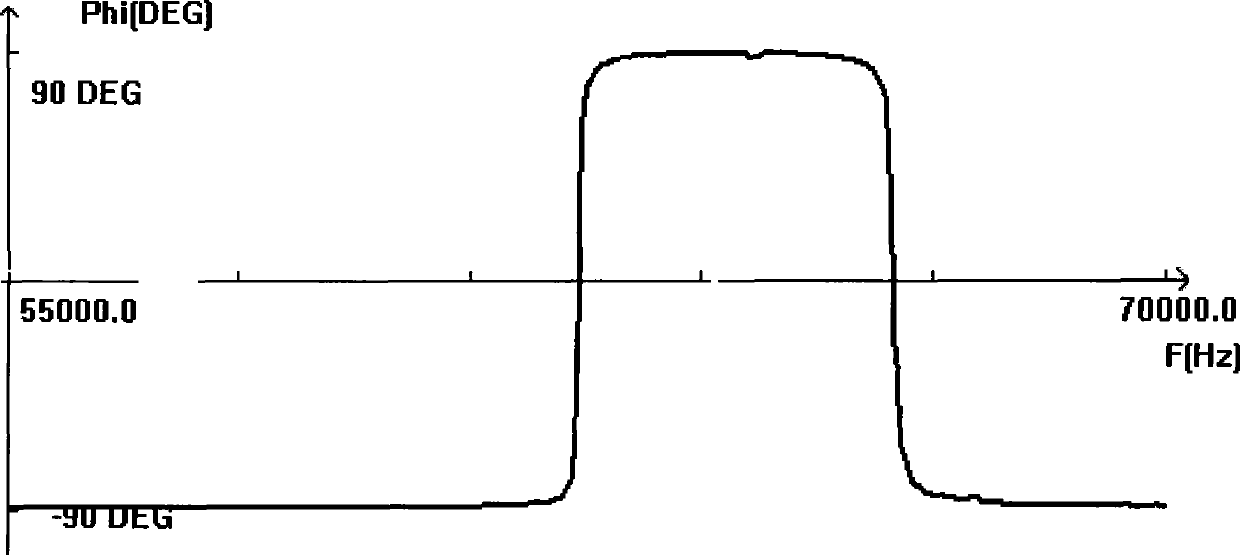
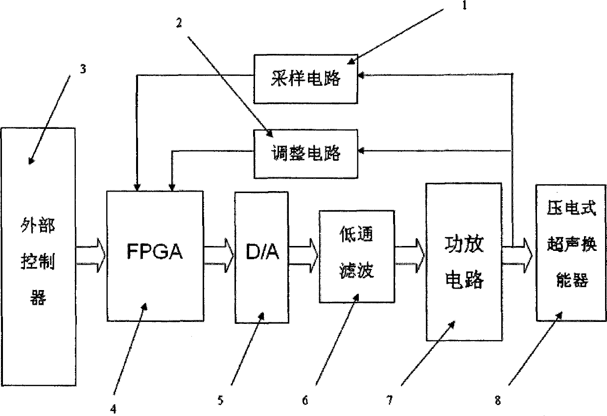
[0027] Such as Figure 2~4 As shown, the driving power supply of the piezoelectric ultrasonic transducer consists of a sampling circuit 1, an adjustment circuit 2, an external controller circuit 3, an FPGA-based processor circuit 4, a D / A conversion circuit 5, a low-pass filter 6, and a power amplifier The circuit 7 etc. are composed.

[0028] The external controller circuit (such as a single-chip microcomputer) sends a pulse control signal to the FPGA, and the FPGA starts to work after receiving the pulse signal;

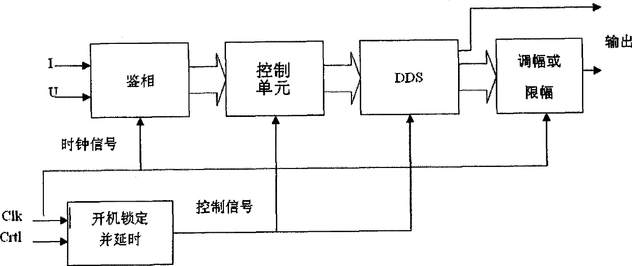
[0029] Such as image 3 As shown, FPGA integrates phase identification, phase locking, DDS function and PID frequency tracking algorithm (the unit to realize the algorithm is image 3 The control unit in the control unit), DDS is the direct digital frequency synthesizer, first load and register the input frequency control word; through the internal phase accumulator, the phase of the frequency control word is accumulated in each clock cycle to obtain a phase valu...


PUM


Abstract

The invention discloses a dielectric ultrasonic transducer driving power, comprising a main controller, a sampling circuit, an adjusting circuit and a driving circuit; the sampling circuit and the adjusting circuit gain signals from the dielectric ultrasonic transducer; the output terminal of the sampling circuit and the adjusting circuit is connected with the main controller which receives the signals emitted by external controls and is connected with the dielectric ultrasonic transducer by the driving circuit; the main controller comprises a phase demodulation unit, a control unit, a direct digital frequency synthesizer, an amplitude modulating and limiting unit; the phase demodulation unit is connected with the output signal of the sampling circuit; the phase demodulation unit, the control unit, the direct digital frequency synthesizer and the amplitude modulating and limiting unit are sequentially connected in series and subsequently output the signals to the driving circuit. Compared with ultrasonic powers based on DSP and other controllers, the driving power has the advantages of rapid phase locking speed, high precision, programmable adjustment of output power, etc.

Description

technical field [0001] The invention belongs to the field of electronic technology, and relates to a piezoelectric ultrasonic transducer driving power supply. Background technique [0002] The piezoelectric ultrasonic transducer and its driving power are the core components of thermosonic bonding equipment. Piezoelectric ultrasonic transducers include piezoelectric transducers, horns, and bonding tools. Among them, the piezoelectric transducer converts the ultrasonic frequency electrical signal into mechanical vibration of the same frequency through the electrostrictive effect, and the mechanical vibration is transmitted to the bonding tool through the horn, so that the bonding tool generates vibration of a certain amplitude. Vibration at ultrasonic frequencies promotes the formation of a clean surface between the two metals and mutual diffusion and welding together. [0003] In the thermosonic bonding equipment, the amplitude output of the piezoelectric ultrasonic transdu...

Claims


Application Information

Patent Timeline
IPC IPC(8): B23K20/10B06B1/06
Inventor 王福亮邹长辉乔家平
Owner CENT SOUTH UNIV
Why Eureka
Try Eureka