Draft tube type jet flow reactor and method for preparing isocyanate using the same
A technology of a jet reactor and a guide tube, which is applied in the direction of chemical methods, chemical instruments and methods, preparation of isocyanic acid derivatives, etc. to make gas medium react with gas medium, and can solve heat exchanger blockage and heat exchanger deposition , poor heat transfer, etc.
- Summary
- Abstract
- Description
- Claims
- Application Information
AI Technical Summary
Problems solved by technology
Method used
Image
Examples
Embodiment 1
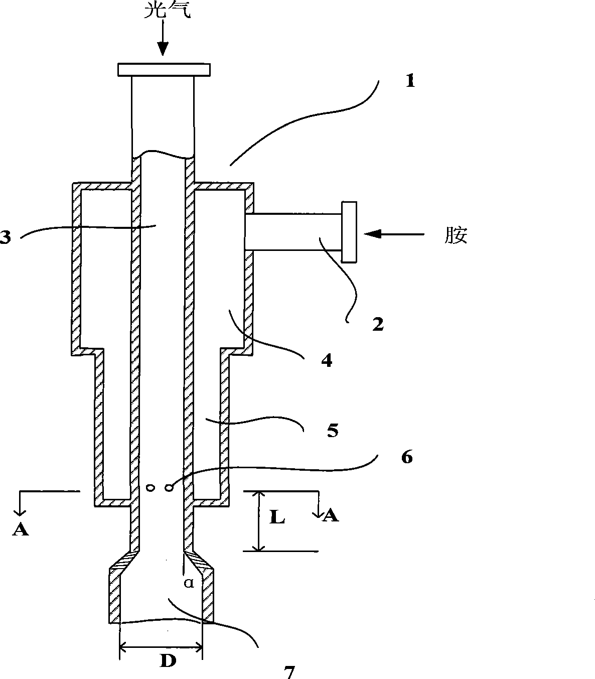
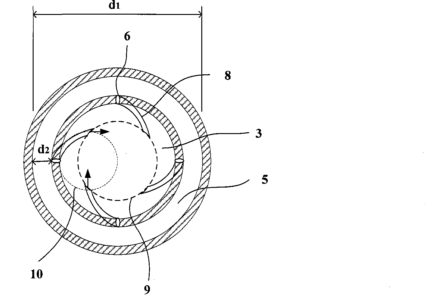
[0048] 4,4'-dicyclohexylmethanediamine (HMDA), phosgene and nitrogen flowed into the reactor continuously through their respective feed pipes at a molar ratio of 1:4:1. The downstream of the reactor is connected with a gas jet absorber (for condensation) and an excess phosgene and hydrogen chloride absorption tower. HMDA, phosgene, and nitrogen enter the figure 1 The indicated reactor fronts were respectively preheated to 360°C. The HMDA vapor is diluted with nitrogen that is 1 times the molar number of the HMDA vapor to form a mixture, and then injected into the guide tube through 6 transverse holes opened on the wall of the inner feed tube, the transverse holes and the guide tube The inner diameter is 1.5mm, the inner diameter of the inner feeding pipe is 12mm, the inner diameter of the outer feeding pipe is 30mm, the inner diameter of the annular space 5 is 20mm, the distance between the transverse hole and the bottom of the annular space is 1cm, the distance between the t...
Embodiment 2
[0055] 4,4'-dicyclohexylmethanediamine (HMDA), phosgene and nitrogen are continuously flowed into such as figure 1 In the shown reactor, HMDA, phosgene, and nitrogen enter into such as figure 1The indicated reactor fronts were each preheated to 360°C. Using a reactor similar to Example 1, nitrogen and HMDA vapor are injected into the guide tube through 4 transverse holes opened on the wall of the inner feed tube, the inner diameter of the transverse holes and the guide tube is 2.0mm, and The inner diameter of the feeding tube is 12mm, and the inner diameter of the first dotted circle is 0.7 times of the inner diameter of the inner feeding tube, and other dimensions and conditions are the same as in Example 1. The vacuum in the reaction tube is -400mbar, the flow velocity of the amine vapor and nitrogen gas flowing through the transverse hole is about 34m / s, and the phosgene flow velocity before mixing is about 8m / s. After leaving the reaction tube of the reactor, the reactio...
Embodiment 3
[0057] Isophoronediamine (IPDA), phosgene and nitrogen enter in the reactor identical with embodiment 1 with the mol ratio of 1:4:1, before entering reactor, IPDA, phosgene and nitrogen are preheated earlier respectively To 320°C, under almost the same reaction conditions as in Example 1, the yield of IPDI was 98.8% of the theoretical value.
PUM
 Abstract
Description
Claims
Application Information
 - R&D
- Intellectual Property
- Life Sciences
- Materials
- Tech Scout
- Unparalleled Data Quality
- Higher Quality Content
- 60% Fewer Hallucinations
Browse by: Latest US Patents, China's latest patents, Technical Efficacy Thesaurus, Application Domain, Technology Topic, Popular Technical Reports.
© 2025 PatSnap. All rights reserved.Legal|Privacy policy|Modern Slavery Act Transparency Statement|Sitemap|About US| Contact US: help@patsnap.com


