Self-volatilization system of evaporator condensation water

A technology of condensate water and evaporator, applied in the direction of preventing condensate water, etc., can solve the problems of drainage pipes affecting the environment, wasting energy, and increasing energy consumption in operation

Inactive Publication Date: 2009-02-25
上海上菱科技开发有限公司
View PDF0 Cites 2 Cited by
  • Summary
  • Abstract
  • Description
  • Claims
  • Application Information

AI Technical Summary

Problems solved by technology

[0005] 1. Collect the condensed water in the water collection tray of the equipment, and install auxiliary heating or auxiliary fans on the equipment to directly force volatilization. This method needs to increase auxiliary devices for drainage or water volatilization, and its disadvantages: ①Increasing equipment cost; ②Increased operating energy consumption
[0006] 2. Connect the drainage hose to the water pan of the equipment and directly discharge it to the external drainage pipe. The defects: ①The laying of the drainage pipe will affect the environment and there is a hidden danger of leakage, especially not suitable for some occasions such as clean workshops , control room and other places; ②During the discharge of condensate water, the cooling capacity of condensate water is also discharged, wasting energy

Method used


Image

  • Self-volatilization system of evaporator condensation water

Examples


Embodiment Construction

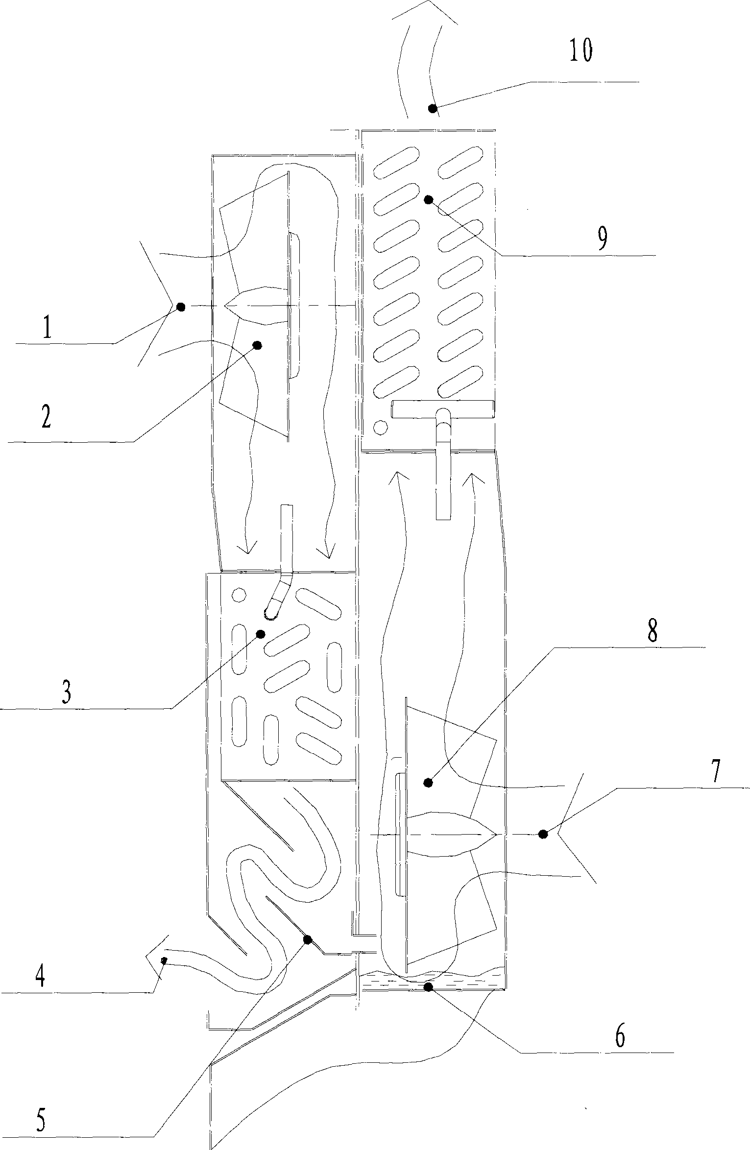
[0012] In the implementation of Fig. 1, when the refrigeration cycle is working, the evaporator fan (2) circulates, and the air in the cooled space is forced to be sucked from the evaporator air inlet (1), and the heat is exchanged through the evaporator (3). The heat is transferred to the refrigerant to complete the gasification process of the refrigerant. At the same time, the moisture in the air condenses into water on the surface of the evaporator. The cooling air returns to the cooled space from the air outlet (4) of the evaporator, and the condensed water passes through the The plate (5) flows into the water accumulation tray (6) at the bottom of the condenser fan (8), and the circulation of the condenser fan fan (8) forces external air to be sucked in from the condenser air inlet (7), and the air passes through the accumulation of water Part of the condensed water evaporates on the water surface of the pan, and after lowering the temperature, it mixes with the tiny water...


PUM


Abstract

The invention provides a self-volatilization system of a condensation water of a steam compression type refrigeration and air-conditioning device. The self-volatilization system is based on the synchronous working principle that in the steam compressor type refrigeration process, the operation of a compressor, the operation of a condensation blower fan (8) and the condensed water of an evaporator (3) generate three states. The condensed water of the evaporator is introduced to a water accumulating disk (6) through a water deflector (5); the water accumulating disk (6) is installed on an air suction flow passage on the side of a condenser (9). When a device works, the condensed water leaves the water accumulating disk through high-speed rotating circulation centrifugal fan impellers of the condensation blower fan (8), and is mixed with the air sucked on the side of the condenser, and the mixture passes through the radiating surface of the condenser (9), so as to synchronously achieve the evaporation of the condensed water and the condensation of a refrigerant. In the invention, devices for assisting heating or assisting the fan do not need to be added to the water accumulating disk, and a pipeline for discharging water to the outside do not need to be installed. The invention overcomes the shortcoming of the prior condensed water processing method, effectively utilizes the cold energy of the condensed water of the evaporator, reduces the cost, saves the energy resource and protects the environment.

Description

Technical field [0001] The invention relates to a new scheme of a condensate water self-volatility system of an evaporator of vapor compression refrigeration and air conditioning equipment. Background technique [0002] Vapor compression refrigeration and air-conditioning equipment generally adopts the refrigeration principle of refrigerant phase change. The high-temperature and high-pressure gaseous refrigerant discharged from the compressor enters the condenser and is forcibly cooled into a high-pressure and medium-temperature liquid refrigerant. After flowing, the low-temperature and low-pressure liquid refrigerant enters the evaporator, absorbs the heat in the cooled space through phase change, and then becomes a gaseous state before entering the compressor. This reciprocating cycle ensures the temperature in the cooled space. [0003] The vapor compression refrigeration cycle using air forced convection draws in external air through the condenser fan and flows through t...

Claims


Application Information

Patent Timeline
Patent Type & Authority Applications(China)
IPC IPC(8): F24F13/22
Inventor 邱月刚
Owner 上海上菱科技开发有限公司
Why Eureka
Try Eureka