Photoresist apparatus for removing edge

A kind of edge light, resist technology, used in optics, nonlinear optics, photosensitive material processing and other directions

Active Publication Date: 2013-11-20
K TRONICS (SUZHOU) TECH CO LTD +1
View PDF10 Cites 0 Cited by
  • Summary
  • Abstract
  • Description
  • Claims
  • Application Information

AI Technical Summary

Problems solved by technology

[0006] The purpose of the present invention is to provide a device for removing edge photoresist, which can effectively solve the technical defects of existing devices such as easy sputtering of traditional Chinese medicine on the substrate and poor formation

Method used


Image

  • Photoresist apparatus for removing edge
  • Photoresist apparatus for removing edge

Examples


Embodiment Construction

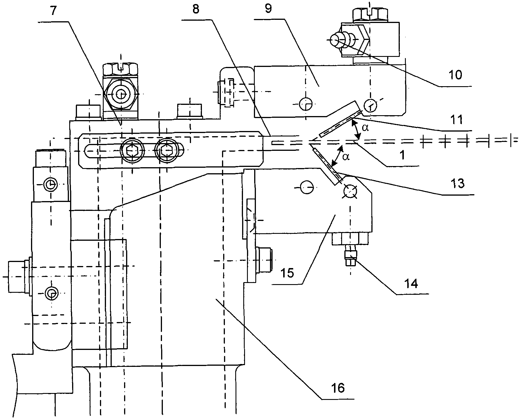
[0024] figure 1 It is a schematic diagram of the structure of the device for removing edge photoresist of the present invention. Such as figure 1 As shown, the device for removing edge photoresist includes a device main body 7, and a discharge pipe 16 for generating negative pressure is arranged in the device main body 7. The upper part of the discharge pipe 16 is a discharge pipe opening 8. In the nozzle 8, the residual liquid on the edge of the glass substrate 1 is sucked from the nozzle 8, and the residual liquid includes dissolved photoresist and residual chemical liquid. The device main body 7 is also fixedly connected with an upper connector 9 and a lower connector 15, the upper end of the upper connector 9 is fixedly connected with the upper liquid inlet 10 for introducing chemical liquid, and the lower end is provided with an end facing the glass substrate 1 at an angle of α. The upper injection needle 11 for spraying the chemical liquid; the lower end of the lower...


PUM


Abstract

The invention relates to an edge-removing optical resist device which comprises a device main body. A racking pipe for pumping residual liquid on the edge of a glass substrate through negative pressure is arranged in the device main body; an upper spray needle and a lower spray needle for spraying chemical liquid medicine at the end part of the glass substrate in a sloping direction from the upper part and the lower part are connected to the device body. By changing an inlet pipe duct and the spray direction of the chemical liquid medicine, and arranging the racking pipe with the negative pressure, the invention avoids gas liquid interference appearing in the use of the prior device, reduces ill probability formation caused by sputtering the chemical liquid medicine on the glass substrate, saves nitrogen at the same time, and reduces manufacture cost.

Description

technical field [0001] The invention relates to a device for removing photoresist used in the production of liquid crystal display panels, in particular to a device for removing edge photoresist. Background technique [0002] The main display function device in a liquid crystal display (LCD) is a liquid crystal panel. The structure of a liquid crystal panel is generally composed of two upper and lower substrates, with a liquid crystal layer in the middle. The display principle is to use the dielectric anisotropy and conductive properties of liquid crystal molecules. Anisotropy, corresponding electrodes are formed on the upper and lower substrates, so that an electric field is generated between the two substrates. When an electric field is applied, the alignment state of the intermediate liquid crystal molecules is converted, resulting in various photoelectric effects. LCDs with multiple pixel electrodes in a matrix array on one substrate and common electrodes on the other su...

Claims


Application Information

Patent Timeline
Patent Type & Authority Patents(China)
IPC IPC(8): G03F7/42G02F1/1333
Inventor 宋瑞涛陈祥麟张学智郑铁元王晏酩张荣军苏九端
Owner K TRONICS (SUZHOU) TECH CO LTD
Why Eureka
Try Eureka