Synchronizing system and method for virtual cascade of light transportation network

A technology of optical transport network and synchronization system, applied in the field of optical communication, which can solve the problems of degraded output service clock quality, unfavorable recovery clock, unmeasurable jitter amplitude, etc., and achieve the effect of solving the degradation of clock jitter index and suppressing jitter

Inactive Publication Date: 2009-02-25
HUAWEI TECH CO LTD
View PDF0 Cites 11 Cited by
  • Summary
  • Abstract
  • Description
  • Claims
  • Application Information

AI Technical Summary

Problems solved by technology

The virtual cascade delay compensation unit aligns the 4-way OPU1, but the interval between the aligned OPU1-4V frames is also random, which is equivalent to providing a random tracking clock for the asynchronous demapping unit, which is not conducive to recovering A clock with satisfactory jitter specifications
Therefore, although this solution can synchronize the OTU1 of the branch to a system clock, the jitter introduced by the synchronization link cannot be measured, and the asynchronous demapping unit cannot effectively filter it, which eventually deteriorates the quality of the output service clock

Method used


Image

  • Synchronizing system and method for virtual cascade of light transportation network
  • Synchronizing system and method for virtual cascade of light transportation network
  • Synchronizing system and method for virtual cascade of light transportation network

Examples


Embodiment 1

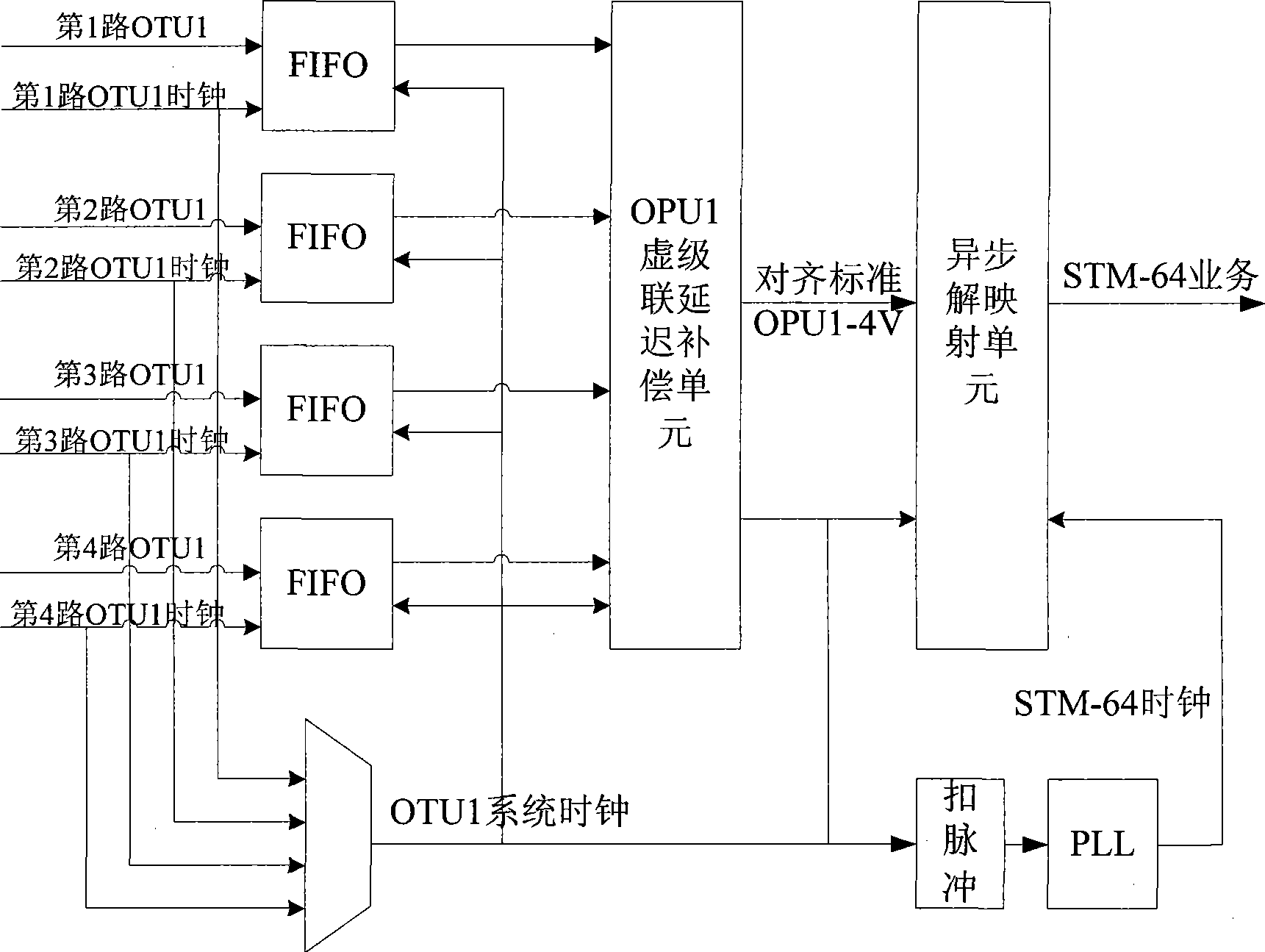
[0043] Such as Figure 5 As shown, the embodiment of the present invention provides an OTN virtual concatenation synchronization system. The system includes five units, which are synchronization unit, virtual concatenation delay compensation unit, asynchronous demapping unit, smooth service acquisition unit and service data recovery unit. Each unit is described in detail below.

[0044] 1. Synchronization unit

[0045] The synchronization unit completes the clock synchronization processing of 4 channels of OTU1, generates synchronous control information, adjusts the pointers of the synchronous control information of each branch according to the FIFO waterline, and generates the synchronous optical channel payload unit and the synchronous optical channel payload unit of the branch. The corresponding notched clock of the load unit.

[0046] In the prior art, due to the difference between the synchronized system clock and the tributary clock, the position of the synchronized O...

Embodiment 2

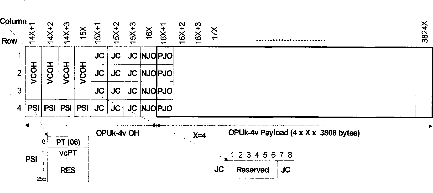
[0096] Such as Figure 10 As shown, the embodiment of the present invention also provides a virtual concatenation synchronization method in an optical transport network. In the present embodiment, adopt fixed-point floating mode, at first, define two free bytes of OTU1 respectively as positive and negative adjustment position, for example define the 1st row of OTU1, the 14th byte is OPU1 negative adjustment position; Line 1, the 15th byte is the positive adjustment position of OPU1. During implementation, bytes at other positions can also be selected as the positive and negative adjustment positions of the OPU1, which is not limited to the method for defining the positive and negative adjustment positions in this embodiment. The positive and negative adjustment positions are relatively fixed at the position of the OTU1, so as to make the OPU1 float at a fixed position.

[0097] After defining the positive and negative adjustment positions, the five steps of synchronization, ...


PUM


Abstract

The invention discloses a virtual concatenation synchronization system in an optical transport network (OTN) and a method thereof, belonging to the field of optical communications. The system comprises a synchronization unit, a virtual concatenation delay compensation unit, an asynchronous demapping unit, a smooth service acquisition unit, and a service data recovery unit. The method comprises the steps of carrying out virtual concatenation delay compensation by using fixed-point floatation of an optical channel payload unit (OPUk), and recovering service data by combining asynchronous demapping during synchronization process. The technical proposal provided in the invention can effectively inhibit jitter due to synchronization and virtual concatenation delay compensation, thereby solving the deterioration problem of clock jitter performance arising from transport of constant bit rate services via virtual concatenation in the OTN.

Description

technical field [0001] The invention relates to the field of optical communication, in particular to a virtual concatenation synchronization system and method in an optical transport network (OTN, Optical Transport Network). Background technique [0002] With the gradual commercialization of OTN equipment, there is an increasing demand for using OTN equipment to carry large bandwidth. Utilizing the virtual concatenation technology of OTN, OTN equipment can carry large-bandwidth services, such as STM-64, 10G Ethernet, and 40G POS. OTN's virtual concatenation technology divides large-bandwidth services into several network-supported particles for transmission, and only needs to support large-bandwidth processing at both the sending and receiving ends. [0003] Such as figure 1 Shown is the OTN virtual concatenation structure. If the client signal is loaded with X OPUk (Optical Channel Payload Unit, optical channel payload unit) (wherein, k=1, 2, 3, respectively correspondin...

Claims


Application Information

Patent Timeline
Patent Type & Authority Applications(China)
IPC IPC(8): H04J3/06H04Q11/00
CPCH04J3/1652H04J2203/0094
Inventor 石磊董娟王晨王秀英
Owner HUAWEI TECH CO LTD
Why Eureka
Try Eureka