Emergency supply unit with a ram-air turbine adapted to be driven by an air stream and with an energy converter for aircraft

A technology of energy converter and ram air, which is applied in the direction of engine components, gas turbine devices, engines, etc., can solve the problems of difficult installation location, increased possibility of failure, large mechanical load, etc., to save space, increase operating reliability and failure safety effect

Inactive Publication Date: 2012-04-04
AIRBUS OPERATIONS GMBH
View PDF0 Cites 1 Cited by
  • Summary
  • Abstract
  • Description
  • Claims
  • Application Information

AI Technical Summary

Problems solved by technology

[0004] However, the mechanical design of known ram air turbines is highly complex, since the rotational movement of the radial thrusters has to be transmitted through the boom to a hydraulic pump arranged in the landing flap track cover by means of a mechanical transmission Requires a lot of maintenance and increases the possibility of failure
Furthermore, if the radial thruster is suddenly swiveled out, the radial thruster is suddenly exposed to the air flow, which results in a considerable mechanical load and also increases the probability of failure
In addition to mounting into the landing flap track cover, different mounting locations may have considerable difficulties due to the radial thrusters
In addition, the landing flap track covers have to be oversized in order to accommodate the known ram air turbines, which leads to aerodynamic asymmetries which have to be compensated by suitable control, guide and / or adjustment surfaces in order to guarantee a precise straight line Fly while sustaining aerodynamic losses
Loss of aerodynamics in turn leads to increased fuel consumption
Finally, the lines from the hydraulic pumps of the ram air turbines must pass through the entire wing up to the aircraft's hydraulic nodes, usually located in the area below the wing box, which further increases the weight and potential for failure of the entire system

Method used


Image

  • Emergency supply unit with a ram-air turbine adapted to be driven by an air stream and with an energy converter for aircraft
  • Emergency supply unit with a ram-air turbine adapted to be driven by an air stream and with an energy converter for aircraft
  • Emergency supply unit with a ram-air turbine adapted to be driven by an air stream and with an energy converter for aircraft

Examples


Embodiment Construction

[0017] In the figures, identical structural elements bear the same reference signs in each case.

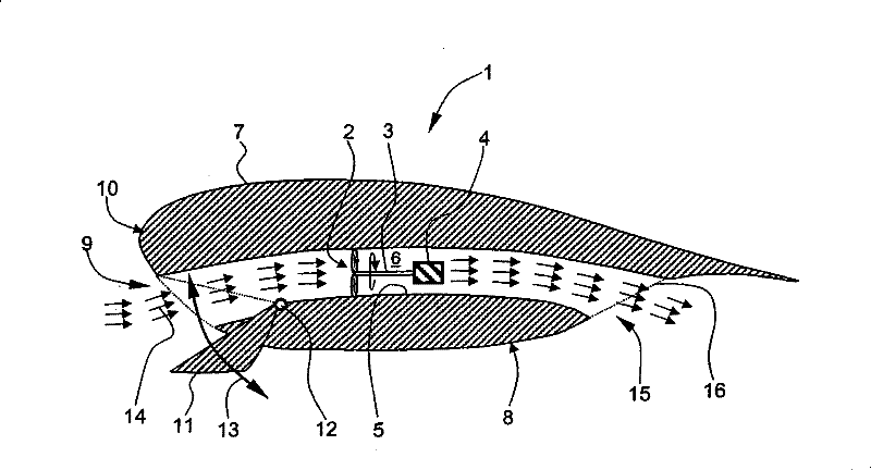
[0018] figure 1 is a schematic sectional view of the emergency energy supply unit.

[0019] The emergency energy supply unit 1 according to the invention comprises a ram air turbine 2 and other components directly connected via a drive shaft 3 to an energy converter 4 , i.e. without the intervention of transmission elements, said elements being substantially coaxially surrounded by a housing 5 so that Air flow channel 6 is formed.

[0020] The housing 5 or the flow channel 6 preferably has a circular cross-sectional geometry, but may also have an at least partially elliptical, oval or angular cross-sectional geometry. For example, housing 5 may be formed using ducting, flexible tubing or the like that substantially concentrically surrounds ram air turbine 2 .

[0021] The drive shaft 3 optionally has a coupling not shown. Thus, the ram air turbine 2 can be started under no-lo...


PUM


Abstract

The invention relates to an emergency supply unit (1) with a ram-air turbine (2) which can be driven by an air stream (14) and with an energy converter (4) for at least partly maintaining the functioning of a hydraulic system and / or electrical system on board an aircraft in an emergency situation, wherein the energy converter (4) can be driven by means of the ram-air turbine (2) and the emergencysupply unit (1) can selectively be brought into a standby mode or into an operating mode.; According to the invention, at least the ram-air turbine (2) is surrounded substantially concentrically by acasing (5) forming a flow channel (6) and the energy converter (4) is directly coupled to the ram-air turbine (2) via a drive shaft (3) and the air stream (14) can be delivered to the ram-air turbine(2) through at least one air inlet (9, 17, 18), wherein the spatial position of the ram-air turbine (2) remains substantially unchanged when changing between the standby mode and the operating mode. The integration of the ram-air turbine (2) into the flow channel (6) results in a very compact and space-saving design of the emergency supply unit (1) according to the invention, thus offering a plurality of additional installation options, for example in the region of the landing flap rail covering (8) below a wing (7) of an aircraft.; Moreover, the substantially completely encapsulated formation of the emergency supply unit (1) without a pivot arm and with direct coupling of the ram-air turbine (2) to the energy converter (4) through the drive shaft (3) is structurally simple and therefore permits largely maintenance-free operation with greater fail safety.

Description

technical field [0001] The invention relates to an emergency energy supply unit having a ram air turbine which can be driven by an air flow and an energy converter which is used in an emergency situation to at least partially maintain an onboard hydraulic system and / or Or the function of an electrical system in which the energy converter can be driven by means of a ram air turbine and the emergency energy supply unit can be selectively brought into a standby mode or an operating mode. Background technique [0002] At least one so-called ram air turbine is currently used in all large passenger aircraft. The ram air turbine is used to at least partially maintain the functionality of the onboard hydraulic system in the event of an emergency, such as a failure of the entire power unit, in order to guarantee a minimum controllability of the aircraft even when diving. The ram air turbine is preferably located under the right wing inside the landing flap track cover ("fairing"). ...

Claims


Application Information

Patent Timeline
Patent Type & Authority Patents(China)
IPC IPC(8): B64D41/00
CPCY02T50/44F05D2220/76Y02E10/725Y02T50/671F05B2220/706F02C7/32F03D1/04Y02E10/72B64D41/007Y02T50/40Y02T50/60
Inventor 乌韦·洪特曼
Owner AIRBUS OPERATIONS GMBH
Why Eureka
Try Eureka