
Real-time particulate matter measuring system

A technology for real-time measurement of particulate matter, applied in measurement devices, particle suspension analysis, sampling, etc., can solve problems such as limited functionality of the system

Inactive Publication Date: 2009-02-25
HORIBA LTD
View PDF0 Cites 12 Cited by
  • Summary
  • Abstract
  • Description
  • Claims
  • Application Information

AI Technical Summary

Problems solved by technology

[0004] Although existing systems for measuring particulate matter are used in many applications, these systems have limited functionality

Method used


Image

  • Real-time particulate matter measuring system
  • Real-time particulate matter measuring system
  • Real-time particulate matter measuring system

Examples


Embodiment Construction

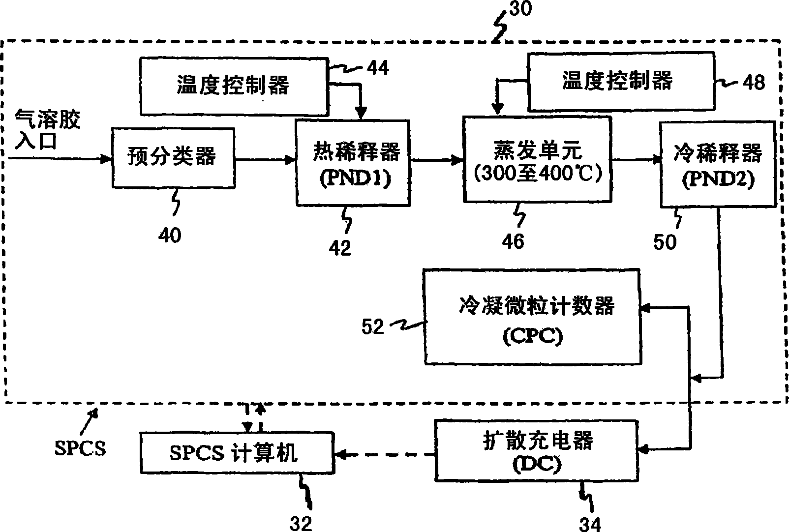
[0017] refer to figure 2 , the particulate matter real-time measurement system includes a solid particle counting system (SPCS) 30 , an SPCS computer 32 , and a diffusion charger (DC) 34 . SPCS 30 includes pre-classifier 40 , hot diluter ( PND1 ) 42 and associated temperature controller 44 , evaporation unit 46 and associated temperature controller 48 , cold diluter ( PND2 ) 50 , and condensation particle counter (CPC) 52 . The pre-classifier 40 is used to keep the cut-off size of the aerosol in the range of 2.5 to 10 μm. By operating thermodiluter 42 at high dilution air temperature with temperature controller 44, and heating the sample in evaporation unit 46 in the range of 300 to 400°C, particulates formed from volatile materials and sulfate particulates are vaporized into a gaseous state. After cold dilution in cold diluter 50, all particulates and sulfates formed from volatile materials are removed. The solid particles move into the CPC 52 and the concentration of the ...


PUM


Abstract

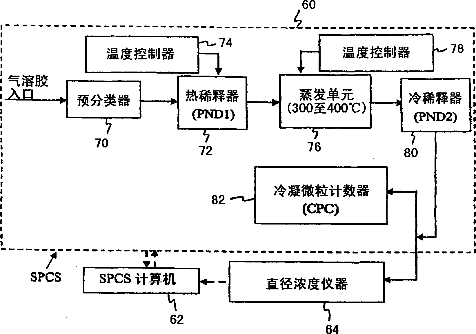
A real-time particulate matter measuring system includes a hot diluter for receiving and diluting aerosol . An evaporation unit receives the diluted aerosol. A cold diluter receives and dilutes the output flow from the evaporation unit. A condensation particle counter receives the diluted output flow and measures the particle number concentration. An integrated device also receives the diluted output flow. The integrated device measures at least one of particle diameter concentration arid particle surface area. The integrated device also measures mass concentration.

Description

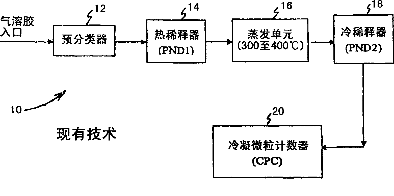
technical field [0001] The invention relates to a real-time measurement system for particulate matter. Background technique [0002] Particulate matter (PM) emissions from internal combustion engines raise public health and environmental concerns. Strict emission standards have been enacted to reduce pollutant emissions from internal combustion engines. Recently, studies have found that with modern technology, the quality based on PM emissions from engines has been significantly reduced. However, the number concentrations of PM emissions from engines have increased significantly. As a result, the emitted particles have a smaller size and a larger surface area. When studying particulate emissions from engines, it is important to measure the particulates correctly. [0003] Existing means of measuring solid particulate counts emitted from light-duty diesel vehicles are in figure 1 10 in the description. System 10 includes pre-classifier 12 , hot diluter ( PND1 ) 14 , eva...

Claims


Application Information

Patent Timeline
Patent Type & Authority Applications(China)
IPC IPC(8): G01N15/00
CPCG01N2001/2261G01N2001/2264G01N1/2202G01N15/06
Inventor 魏强卡尔·E·厄斯特高浅野一朗莱斯利·希尔
Owner HORIBA LTD
Learn More