
Micro-molding finial on surface prepared by laser and preparation method thereof

A surface micro-modeling and top technology, which is applied in laser welding equipment, tailstock/top, turning equipment, etc., can solve the problems of complex rotary top structure, low workpiece positioning accuracy, and increased manufacturing costs, so as to achieve low cost and high efficiency. Processing quality, effect of reducing wear

Inactive Publication Date: 2009-03-04
JIANGSU UNIV
View PDF3 Cites 17 Cited by
  • Summary
  • Abstract
  • Description
  • Claims
  • Application Information

AI Technical Summary

Problems solved by technology

However, the structure of the rotary top is complicated, the manufacturing cost is high, and the clearance problem of the rolling bearing itself leads to poor rigidity of the structure and low positioning accuracy of the workpiece. Therefore, the rotary top is only used for rough turning and semi-finishing turning with low precision and quality requirements. Processing
In the field of top surface treatment, the surface finish is traditionally required to be very smooth. Superfinishing not only increases the manufacturing cost, but also is easily limited by the material properties and processing accuracy.

Method used


Image

  • Micro-molding finial on surface prepared by laser and preparation method thereof
  • Micro-molding finial on surface prepared by laser and preparation method thereof
  • Micro-molding finial on surface prepared by laser and preparation method thereof

Examples


Embodiment Construction

[0017] The specific implementation process of the present invention will be described below by taking a fixed top as an example.

[0018] The laser micromodeling equipment uses a diode-pumped Nd:YAG laser.

[0019] The top is an ordinary fixed top, its material is hard alloy, and the surface is ground.

[0020] The embodiment of the present invention provides a method for preparing a laser surface micro-modeling tip, the steps of which are:

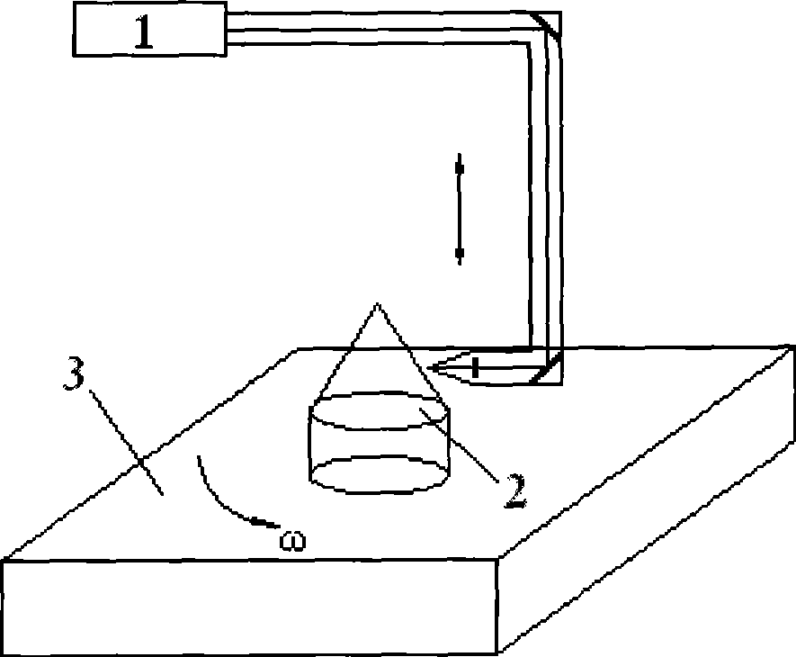
[0021] Step 1: Provide a diode-pumped Nd:YAG laser 1, its basic parameters are: laser power 3W, Q-switched pulse repetition frequency 7.8KHz, wavelength 532nm, pumping current 21-22.8A.

[0022] Step 2: Select a fixed tip 2, the material of which is hard alloy, and the surface is ground and processed.

[0023] The third step: (1) Processing of pit morphology. Install the fixed top 2 on the machine table 3, adjust the laser power density 10 5 -10 7 W / cm 2 , pulse width 30-50ns, wavelength 532nm, pump current 21-22.8A, pulse frequency...


PUM

PropertyMeasurementUnit
Pit depthaaaaaaaaaa

Abstract

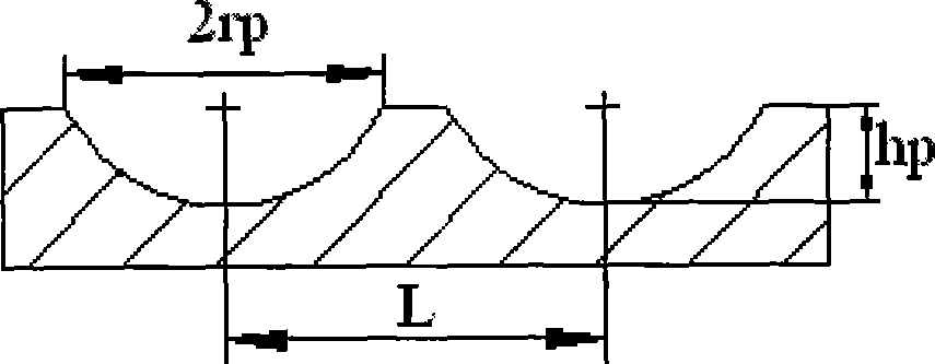
The invention provides a laser surface micro-processing tip and the preparation method thereof. The laser surface micro-processing tip is a metallographic structure, on the tip surface of which a micro-geometrical structure composed of a micro-pit or a cross groove and the combination thereof is formed, wherein the geometric parameters of the pit-shaped micro-geometrical structure are as follows: the pit radius rp is equal to 20 to 80 Mum, the pit depth hp is equal to 2 to 20 Mum, and the adjacent pits space L is equal to 50 to 200 Mum; the geometric parameters of the cross groove-shaped micro-geometrical structure are as follows: the groove width B is equal to 50 to 150 Mum, the groove depth is equal to 5 to 20 Mum, the adjacent groove space D is equal to 400 to 600 Mum, and the groove inclination angle A is equal to 30 DEG to 75 DEG. Since the tip surface is subjected to the laser micro-processing treatment, the laser surface micro-processing tip remarkably improves the wear-resisting performance, improves the lubricating conditions of the tip in the work-piece center hole and reduces the frictional noise, and at the same time, the stored lubricant can be effectively cooled, thereby prolonging the service life of the tip.

Description

technical field [0001] The invention relates to the field of top surface treatment of a machine tool for mechanical processing, in particular to a laser surface micro-modeling top for laser microscopic modification and reshaping treatment on the surface of a fixed top and a preparation method thereof. Background technique [0002] The top is an indispensable tool in machining, and it is divided into a fixed top and a rotary top. The fixed top has the advantages of high positioning accuracy and low manufacturing cost, so it is widely used. When machining parts, the tip moves relatively at high speed in the center hole, causing it to rub against the center hole violently, resulting in high temperature, which can easily cause the tip to burn out or the center hole to bite, affecting the machining accuracy of the workpiece. In addition, the lubricating oil added near the tip can only cool the tip body, but cannot change the nature of the dry friction between the tip and the cen...

Claims


Application Information

Patent Timeline
IPC IPC(8): B23B23/00B23K26/00B23K26/352
Inventor 符永宏张华伟
Owner JIANGSU UNIV
Learn More