Method for detecting cementing quality between tin babbit alloy and lined steel

A technology of tin-based bearing alloy and bonding quality, which is applied in the direction of using sound wave/ultrasonic wave/infrasonic wave to analyze solids, etc., can solve the problems of high work intensity, cumbersome operation, and low detection efficiency, so as to improve detection speed, facilitate instrument adjustment, The effect of high defect detection rate

Inactive Publication Date: 2009-03-11
HUDONG HEAVY MACHINERY
View PDF0 Cites 5 Cited by
  • Summary
  • Abstract
  • Description
  • Claims
  • Application Information

AI Technical Summary

Problems solved by technology

Since the 1:1 detection method of the comparison test block is based on the production of the test block, and the test block needs to be carried to the detection site for comparison, the detection efficiency is low, and the sensitivity dynamic compensation is performed without careful consideration of the actual condition of the tin-based alloy surface of the part. , will cause missed detection of defects
Although the one-time lined steel bottom wave detection method for parts saves the trouble of making comparison test blocks, the multiple reflection wave images of unbonded defects are relatively loosely arranged, and the wave images of repeated reflections are not obvious (the wave velocity of the lined steel is 5840m / s, the wave velocity of tin-based alloy is 3230m / s about 1.8 times), such as Figure 1a and Figure 1b as shown, Figure 1a It is a schematic diagram of the waveform of the bonded part of the primary bottom wave detection method in the prior art, Figure 1b It is a schematic diagram of the waveform of the bonded defect in the primary bottom wave detection method in the prior art
Furthermore, since the surface finish of the probe contact part during the adjustment of the ultrasonic detector is not consistent with the finish of other parts during the actual detection, the detection sensitivity of the part with poor finish will decrease, and the non-dynamic sensitivity compensation will also cause defects. missed detection
[0004] To sum up, when testing the bonding quality of two kinds of composite metals, using the two kinds of ultrasonic detectors used in the current common standards may make the test block, the operation is cumbersome, the detection efficiency is low, and the work intensity is high. , and defects such as insignificant wave images and sometimes insufficient detection sensitivity, and these insufficient factors will directly affect the quality of detection and bring hidden dangers to product quality

Method used


Image

  • Method for detecting cementing quality between tin babbit alloy and lined steel
  • Method for detecting cementing quality between tin babbit alloy and lined steel
  • Method for detecting cementing quality between tin babbit alloy and lined steel

Examples


Embodiment 1

[0038] Next, a detection and analysis will be performed on the bonding state between the tin-based bearing alloy on the upper slider of the marine diesel engine and the lining steel, and the method of the present invention will be used specifically.

[0039] In practical application, the ultrasonic flaw detector of the present invention is the CTS-2000 type, the frequency of the probe is 2.5MHz, and the diameter of the chip inside the probe is Φ20mm.

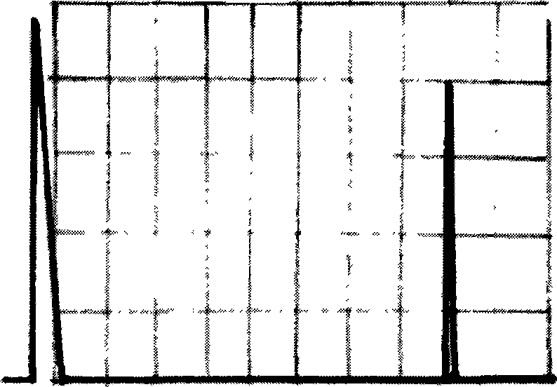
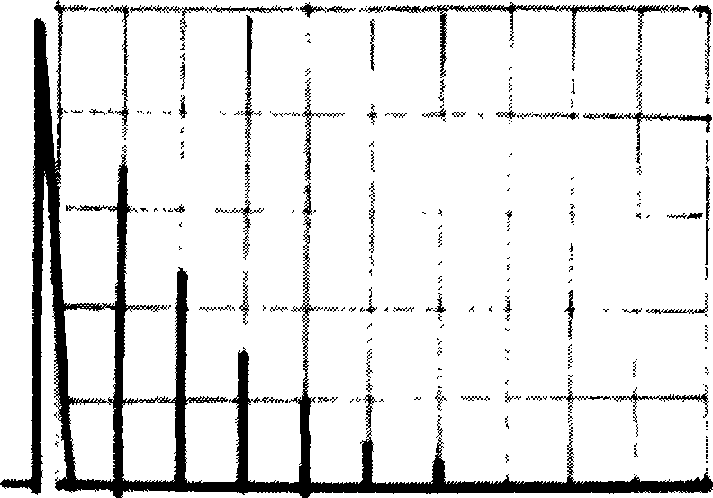
[0040] Adjustment of the ultrasonic detector: Place the probe connected to the instrument on the tin-based bearing alloy surface of the slider with good composite bonding quality. Such as Figure 4 as shown, Figure 4 It is a schematic diagram of the detection state in Example 1 in a method for detecting the bonding quality of tin-based bearing alloy and lining steel of the present invention. The two sides of the slide block of the marine diesel engine in the figure are made of composite metal, and the probe of the detector ne...

Embodiment 2

[0043]Next, a detection and analysis will be performed on the bonding state between the tin-based bearing alloy on the upper thrust block of the marine diesel engine and the lining steel, and the method of the present invention will be used specifically.

[0044] In practical application, the ultrasonic flaw detector of the present invention is the CTS-2000 type, the frequency of the probe is 2.5MHz, and the diameter of the chip inside the probe is Φ20mm.

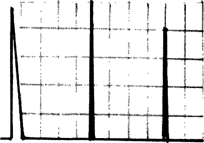
[0045] Adjustment of the ultrasonic detector: Place the probe connected to the instrument on the tin-based bearing alloy surface of the thrust block with good composite bonding quality, such as Figure 5 as shown, Figure 5 It is a schematic diagram of the detection state in Example 2 in a method for detecting the bonding quality of the tin-based bearing alloy and the lining steel of the present invention. One side of the thrust block of the marine diesel engine in the picture is made of composite metal. It is necessary to...


PUM

PropertyMeasurementUnit
diameteraaaaaaaaaa
diameteraaaaaaaaaa
thicknessaaaaaaaaaa

Abstract

The invention relates to a method for detecting the bond quality of Husman metal and lined steel, which comprises the following steps: 1) an ultrasonic inspection device is equipped, a probe is placed on the good bond part of the composite metal; 2) the ultrasonic inspection device is adjusted to lead secondary bottom waves to appear on an oscilloscope screen; 3) the amplitude of 80 percent of the secondary bottom waves on the horizontal timer shaft is adjusted to be 80 percent of the vertical amplitude; 4) the probe is moved line by line on the surface of the composite metal, the moving speed of the probe is not more than 150mm / s, 10 percent of the diameter of the probe is covered between every two lines when detecting; 5) if forest-shaped waves appear on the oscilloscope screen tagging the initial waves, the position has bond defects; and 6) the probe is moved in all directions, the defect waves on the oscilloscope screen are observed, and the demarcation points are found out, and then each demarcation point is linked to enclose the defect area. The invention has the advantages of convenient instrument regulation, more obvious and easily identified defect waves, judging the defect boundaries more easily, high detectable rate for the defects and reducing the working strength.

Description

technical field [0001] The invention relates to defect detection, in particular to a detection method for the composite bonding quality of tin-based bearing alloy and lining steel used in marine diesel engine parts. Background technique [0002] Among diesel engine parts, sliding bearing parts made of tin-based bearing alloys by casting and bonding with lining steel have been widely used, such as sliders, thrust blocks, crosshead bearing caps, bushings, etc. Whether the bonding quality of the two metal composite interfaces of such parts meets the design requirements directly affects whether the design functions of the sliding bearing parts can meet the standards. Therefore, it is very important to accurately detect the bonding quality of the two composite metals. [0003] At present, the evaluation of the bonding quality of these composite metals at home and abroad usually adopts ultrasonic non-destructive testing technology. In the current ultrasonic testing specification...

Claims


Application Information

Patent Timeline
Patent Type & Authority Applications(China)
IPC IPC(8): G01N29/11
Inventor 方海王学志
Owner HUDONG HEAVY MACHINERY
Why Eureka
Try Eureka