Single-phase earth fault positioning device for electrical power distribution network

A single-phase ground fault and positioning device technology, applied in the field of electric power technology and equipment, can solve small faults, can continue to run for 1 to 2 hours under fault conditions, the distribution grid has not been well resolved, manual patrolling It eliminates problems such as the consumption of manpower and material resources for wires, and achieves the effects of easy field operation, high reliability, and cost savings.

Inactive Publication Date: 2009-03-11
NORTH CHINA ELECTRIC POWER UNIV (BAODING) +2
View PDF0 Cites 52 Cited by
  • Summary
  • Abstract
  • Description
  • Claims
  • Application Information

AI Technical Summary

Problems solved by technology

When a single-phase ground fault occurs, the ground current is very small, and it can continue to run for 1 to 2 hours under the fault condition, but the fault point must be found as soon as possible, which raises the problem of fault location
[0003] The problem of single-phase ground fault location in distribution network has not been well solved for a long time. Manual line inspection not only consumes a lot of manpower and material resources, but also prolongs the power outage time, affecting the safety of power supply
Some literature proposes to inject a high-frequency signal from the PT, and detect the signal along the line to determine the fault location, but because the distributed capacitance of the line forms a path for the high-frequency signal, the location is not accurate when it is grounded through a resistor

Method used


Image

  • Single-phase earth fault positioning device for electrical power distribution network
  • Single-phase earth fault positioning device for electrical power distribution network
  • Single-phase earth fault positioning device for electrical power distribution network

Examples


Embodiment Construction

[0024] The technical solution of the present invention will be further described in detail through specific embodiments in conjunction with the description and figures below.

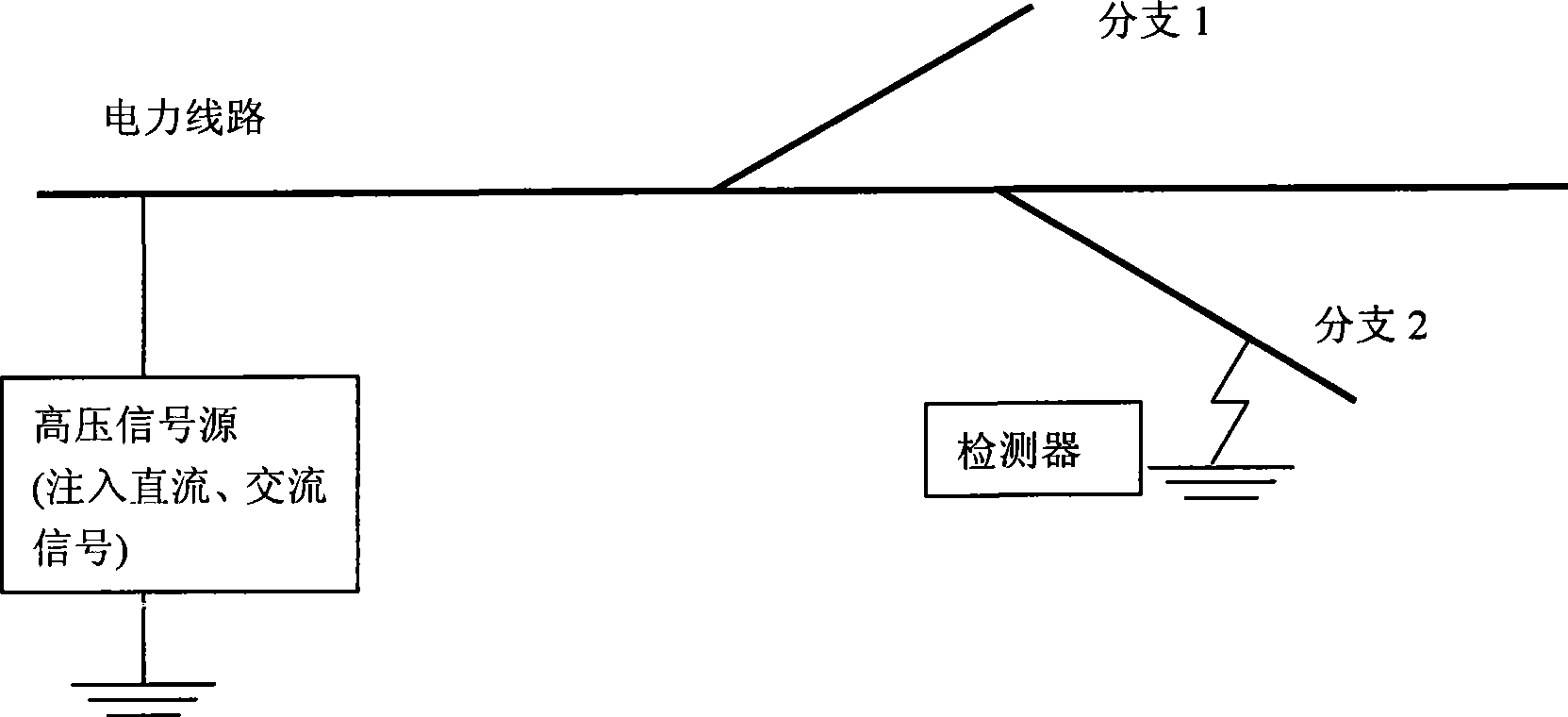
[0025] The principle of a new positioning method proposed by the invention is to determine the section first, and then determine the fault point. After the faulty line is disconnected, a high-voltage DC signal is injected into the faulty phase at the beginning of the line, and the signal detector is used to detect the DC signals flowing through each branch at key branch points along the line, and the section where the fault point is located is determined according to the change of the DC signal. When the fault section is less than 1000m, a high-voltage AC signal is injected into the fault phase at the beginning of the line, and a signal detector is used to detect the AC signal along the line to determine the exact location of the fault. This method is the first of its kind.

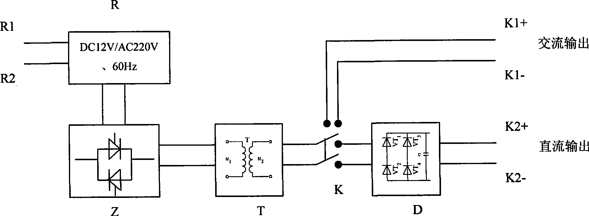
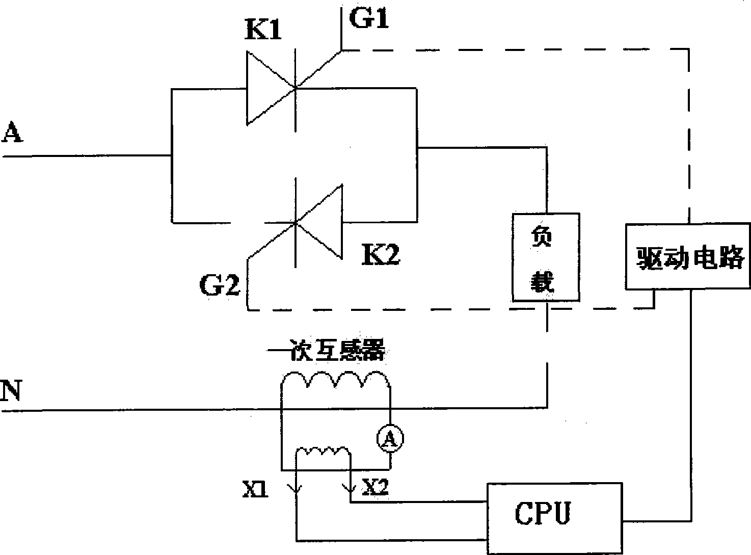
[0026] The positioning dev...


PUM


Abstract

The invention disclose a new positioning method of a distribution network single-phase earth fault, which is applicable to a 3-60 kV neutral point ineffective earth grid. The principle of the positioning method is that: firstly, a high-voltage DC signal is poured into a circuit starting end and the DC signal is detected along the circuit so as to determine a fault area; then a high-voltage AC signal is poured into the circuit starting end, and the AC signal is detected along the circuit so as to determine the position of a fault point. A positioning device developed on the basis of the invention consists of two parts: a high-voltage signal source and a signal detector, wherein, the high-voltage signal source consists of a voltage inverter, a constant flow source, a transformer and a rectifier bridge and is used for pouring a high-voltage DC signal and a high-voltage AC signal; the signal detector comprises a DC detector and an AC detector, wherein, the DC detector consists of a Hall DC detector, a Bluetooth wireless sender and a Bluetooth wireless receiver and is used for measuring the DC signal; while the AC detector consists of an AC electromagnetic field inductor and a signal processing and display segment and is used for measuring the AC signal. The method and the device have mature technique and high reliability.

Description

technical field [0001] The invention belongs to electric power technology and equipment, which is suitable for 3-60kV neutral point non-effectively grounded power grids and can accurately locate single-phase ground faults. Background technique [0002] The 3-60kV distribution network in my country widely adopts the non-effective neutral point grounding method, also known as the small current grounding system, and most of the faults in the small current grounding system are single-phase grounding faults. When a single-phase ground fault occurs, the ground current is very small, and it can continue to run for 1 to 2 hours under the fault condition, but the fault point must be found as soon as possible, which raises the problem of fault location. [0003] The problem of single-phase ground fault location in distribution network has not been well solved for a long time. Manual line inspection not only consumes a lot of manpower and material resources, but also prolongs the power...

Claims


Application Information

Patent Timeline
Patent Type & Authority Applications(China)
IPC IPC(8): G01R31/08
CPCY04S10/522Y04S10/52
Inventor 杨以涵齐郑李砚戚宇林张福华辛晓光
Owner NORTH CHINA ELECTRIC POWER UNIV (BAODING)
Why Eureka
Try Eureka