Movement supporting mechanism for silicon chip surface observation

A support mechanism and a technology on the surface of silicon wafers, which can be used in electrical components, semiconductor/solid-state device manufacturing, circuits, etc., and can solve problems such as large volume, high cost, and unstable movement

Active Publication Date: 2009-03-11
陈百捷 +1
View PDF0 Cites 5 Cited by
  • Summary
  • Abstract
  • Description
  • Claims
  • Application Information

AI Technical Summary

Problems solved by technology

However, the relevant sucker-type products on the market currently have complex structures, large volume, high cost, unstable movement, and are prone to vibration at the limit points of 0° and 90°. These are problems that equipment manufacturers are eager to solve.

Method used


Image

  • Movement supporting mechanism for silicon chip surface observation
  • Movement supporting mechanism for silicon chip surface observation
  • Movement supporting mechanism for silicon chip surface observation

Examples


Embodiment Construction

[0014] The present invention will be described in detail below with reference to the accompanying drawings and embodiments.

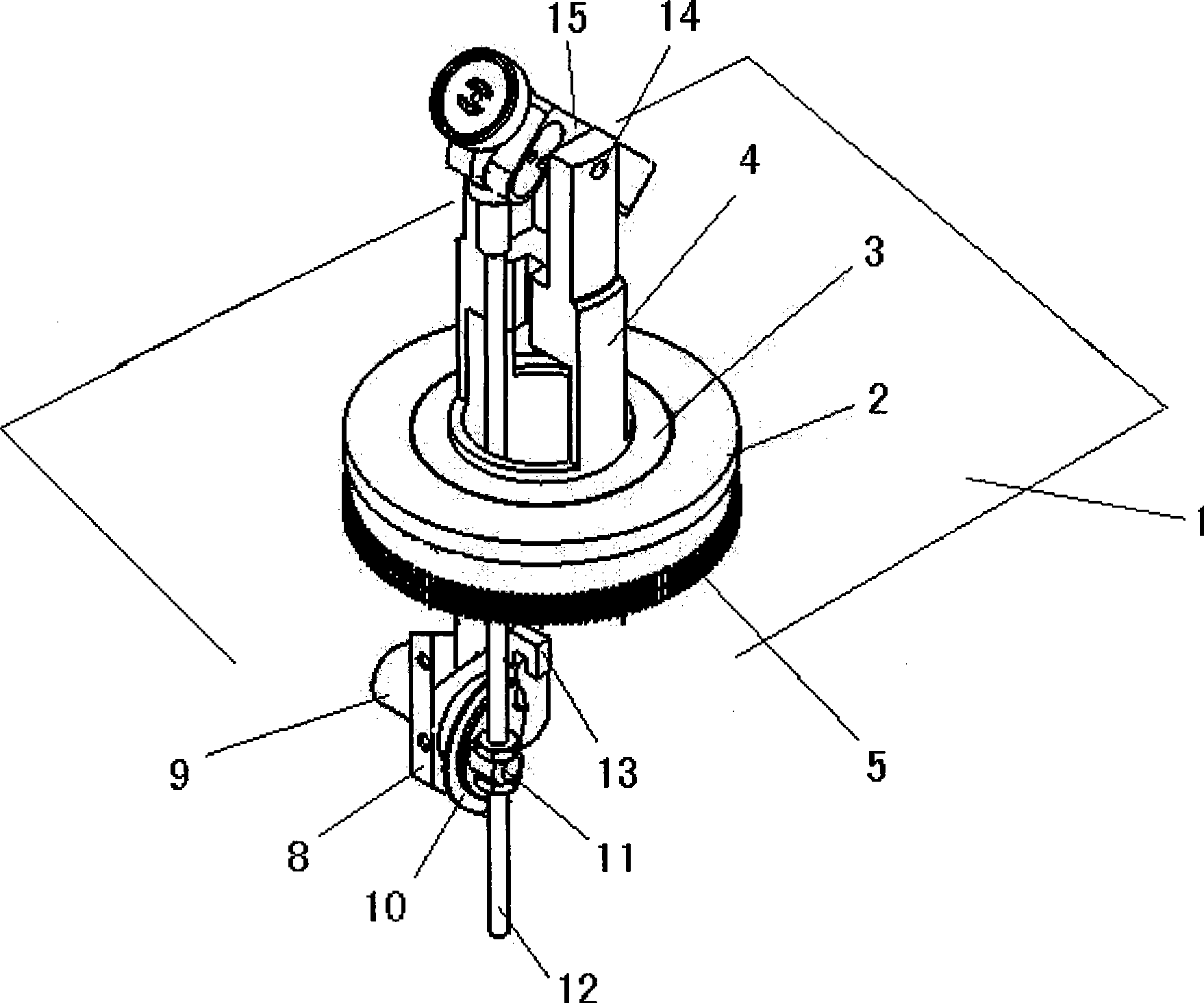
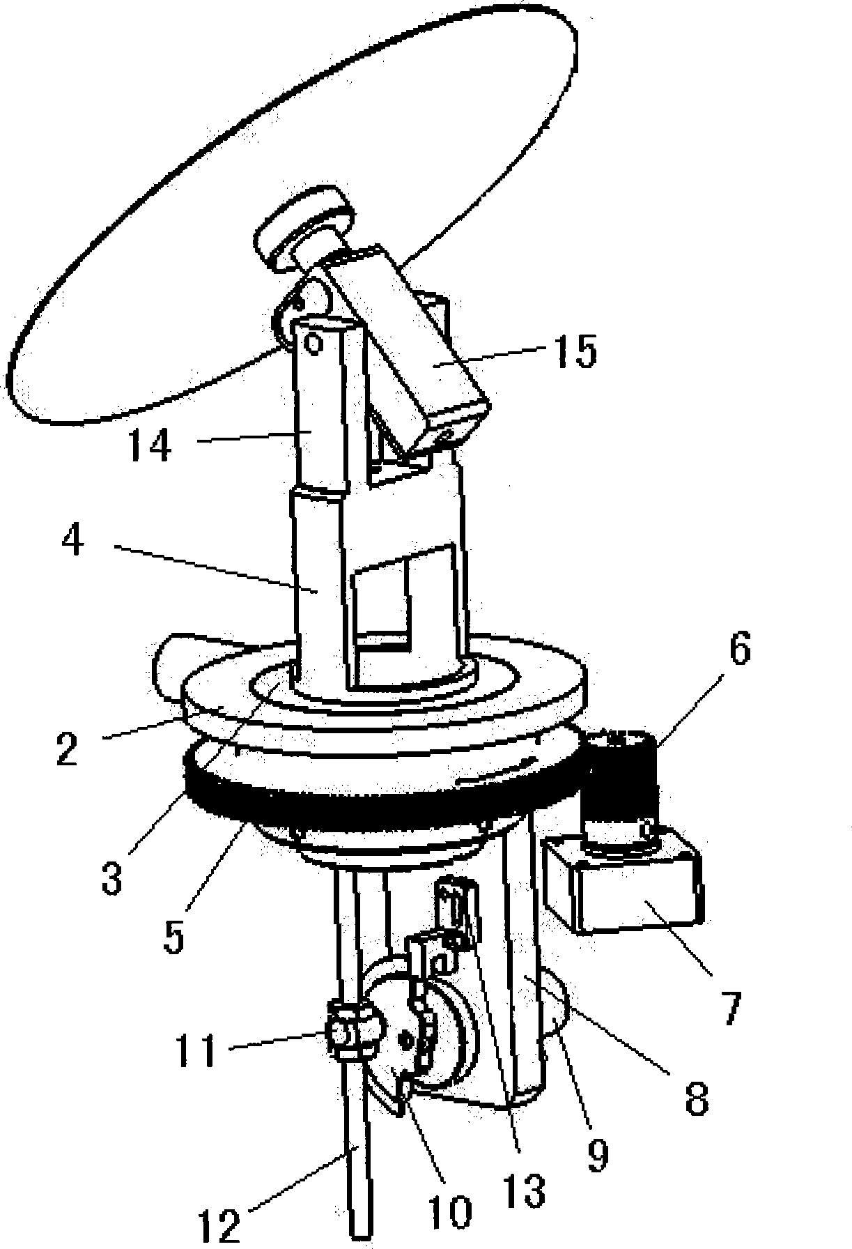
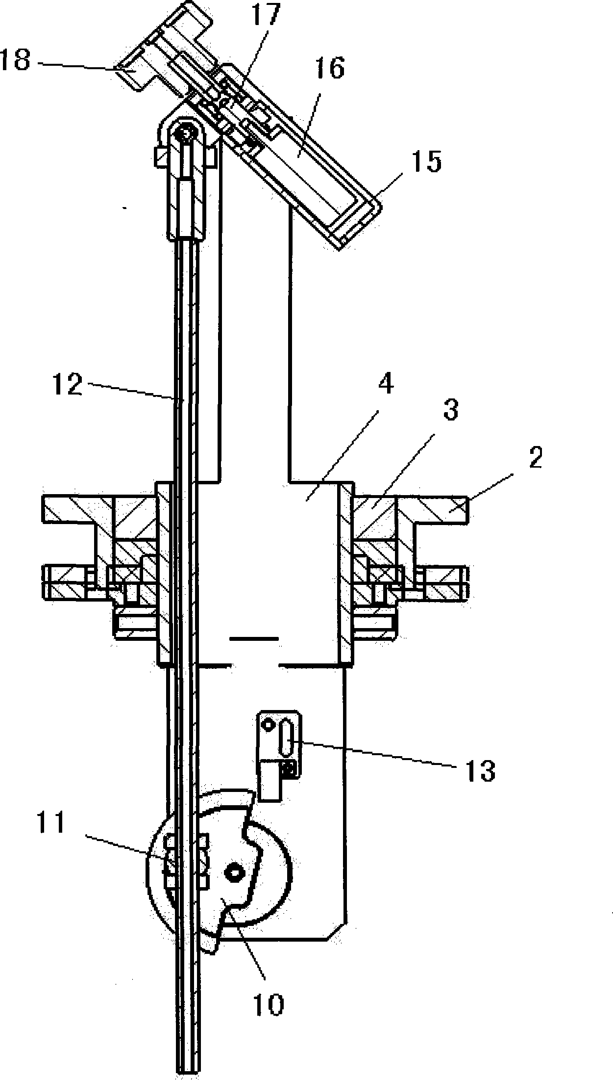
[0015] like Figures 1 to 3 As shown, the present invention includes a horizontal bearing seat 2 fixed on the worktable 1 , and a bearing 3 is arranged in the horizontal bearing seat 2 . A hollow support 4 passes through the bearing 3 and exposes the table 1 at the upper and lower ends. A large gear 5 is fixedly sleeved on the pillar 4 passing through the bottom surface of the worktable 1, and a small gear 6 is meshed with the large gear 5. The pinion 6 is fixed on the output end of the horizontal motor 7, and the horizontal motor 7 is fixed on the worktable. 1 on the attached bracket (not shown in the figure).

[0016] The above-mentioned transmission assembly composed of two meshing gears may also be two gears connected by a toothed belt.

[0017] A wing lug 8 protrudes from the bottom end of the strut 4, a crank motor 9 is fixed on the wing lug 8,...


PUM


Abstract

The invention relates to a moving and supporting mechanism for observing the surface of a silicon chip, comprising a hollow supporting post which is vertically arranged and is driven by a horizontal motor to horizontally rotate, wing lugs respectively extend from the upper end and the lower end of the supporting post, a crank motor is fixed on the wing lug at the lower end, an output shaft of the crank motor is connected with a crank disc, the eccentric point of the crank disc is connected with a hollow link rod by a rotating shaft, a swinging handle of a sucking disc is pivoted between the two wing lugs which extend from the upper end of the supporting post, the front end of the swinging handle of the sucking disc is pivoted on the top of the link rod, an autorotation motor is arranged in a cavity of the swinging handle of the sucking disc, an output end of the autorotation motor is connected with a rotating shaft of the sucking disc, and the rotating shaft of the sucking disc extends out of the swinging handle of the sucking disc to be connected with another sucking disc; and vacuum air channels which are mutually communicated are arranged on the link rod, the swinging handle of the sucking disc, the rotating shaft of the sucking disc and the sucking disc. The sucking disc is driven by the motors of the mechanisms and can carry out rotation, revolution and pitching to form three kinds of composite spherical motion; and the invention solves the problems of pitching matitation and large-area adsorption, and can be widely popularized and applied.

Description

technical field [0001] The invention relates to a silicon wafer inspection device, in particular to a motion support mechanism for observing the surface of a silicon wafer. Background technique [0002] In the current semiconductor manufacturing industry, many processes require the inspection of both sides of the surface of the silicon wafer. At present, the suction cup method is mostly used for inspection. After the suction cup sucks the back side of the silicon wafer, it rotates and swings in the range of 0 to 90°, so that the external defects of the silicon wafer and whether there are contaminated particles can be observed under special light. Determine the coating thickness of the silicon wafer by observing the color of the surface of the silicon wafer (different colors correspond to different thicknesses). However, the related suction cup products currently on the market have complex structures, large volumes, high cost, unstable movement, and are prone to jitter at th...

Claims


Application Information

Patent Timeline
Patent Type & Authority Applications(China)
IPC IPC(8): H01L21/683
Inventor 陈百捷徐伟新姚广军
Owner 陈百捷
Why Eureka
Try Eureka