Damping device for a composite blade

A composite material and vibration damping device technology, which is applied to the supporting elements of blades, components of pumping devices for elastic fluids, liquid fuel engines, etc. question

Active Publication Date: 2009-03-18
SN DETUDE & DE CONSTR DE MOTEURS DAVIATION S N E C M A
View PDF4 Cites 18 Cited by
  • Summary
  • Abstract
  • Description
  • Claims
  • Application Information

AI Technical Summary

Problems solved by technology

[0005] Flutter is a phenomenon that is difficult to predict due to the complexity of the coupling between aerodynamic and mechanical responses
Additionally, mechanical blade vibration damping is often poorly understood

Method used


Image

  • Damping device for a composite blade
  • Damping device for a composite blade
  • Damping device for a composite blade

Examples


Embodiment Construction

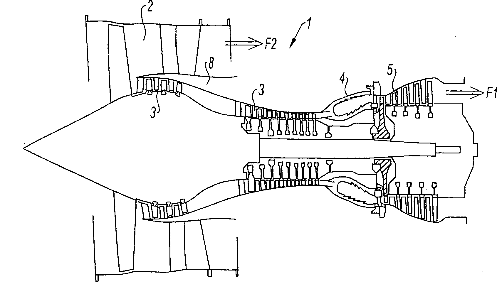
[0050] figure 1 Is a schematic diagram of a turbine, the turbine shown is a twin-rotor bypass turbojet engine 1 . Fan 2 located at the front supplies air to the engine. The air compressed by the fan enters into two concentric flow paths F1 and F2 in two paths. The secondary flow path F2 (or bypass) is directly discharged into the atmosphere and provides the main propulsion thrust. The main flow F1 is led through several compression stages 3 into a combustion chamber 4 where air is mixed with fuel and combusted. The hot gas powers each turbine stage 5, which turns the fan 2 and the compression rotor 3 in rotation. The gas is then vented into the atmosphere.

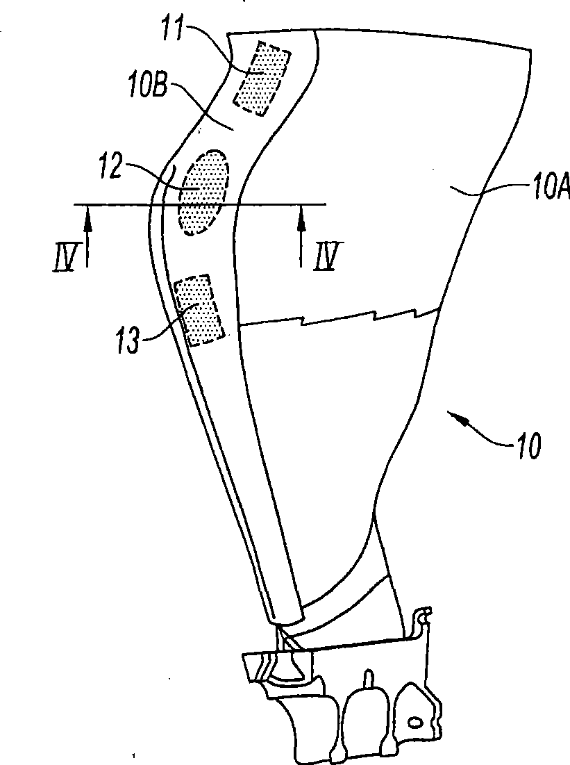
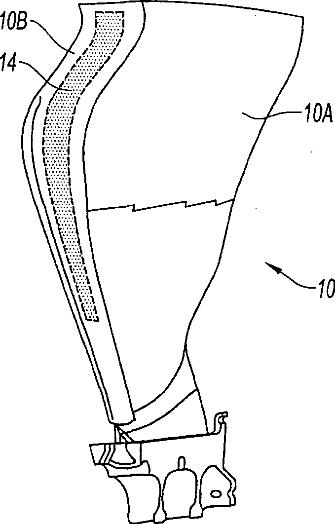
[0051] figure 2 with image 3 A fan blade 10 that may be used on such an engine is shown. This is a blade made of composite material. Typically, the composite portion 10A of the blade consists of fibers or long filaments held together with a thermosetting resin. These fibers or thin filaments are made of carbon o...


PUM


Abstract

The present invention relates to a blade made of composite, comprising a vane (10A) formed of woven filaments impregnated with a thermosetting resin with a protective element (10B) in the region of the leading edge of the vane comprising a part in the form of a rigid strip, said strip being secured to the vane. The blade is characterized in that at least one layer of a viscoelastic material (20, 21) is at least partially interposed between said rigid strip (10Bi, 10Be) and the vane (10A) so as to form, with the protective element, a means of damping the vibrations (11, 12, 13) of the vane.

Description

technical field [0001] The invention relates to the field of turbomachines, to the damping of blades made of composite materials, and in particular to the damping of fan blades of turbojet engines. Background technique [0002] Blades made of carbon fiber composites, especially fan blades, but also low-pressure compressor blades, are produced in different ways. According to one method of manufacture, stacks of unidirectional plies or woven prepregs are formed and placed in a mold prior to compaction and polymerization in an autoclave, respectively defining the individual ply differences. Location. According to another method, woven dry fiber prepregs are prepared and sewn together, or alternatively, a single three-dimensional woven fiber or filament preform is formed, which is then passed through in a closed mold. Injection molding to impregnate it with resin. The blade made in this way is an integral component, including the blade root and the blade surface. It has vari...

Claims


Application Information

Patent Timeline
Patent Type & Authority Applications(China)
IPC IPC(8): F01D5/10F01D5/16F04D29/32F04D29/38F04D29/66
CPCY10S416/50F05D2220/36F05D2300/133F05D2300/501F05D2300/603F01D5/288F01D5/16Y02T50/673Y02T50/67F05C2201/0412Y02T50/672F05C2253/04F01D5/282F01D5/147F05C2251/02F04D29/324F05D2240/303Y02T50/60F05D2300/43
Inventor 索恩·勒·鸿让-皮埃尔·弗朗西斯·隆巴徳
Owner SN DETUDE & DE CONSTR DE MOTEURS DAVIATION S N E C M A
Why Eureka
Try Eureka