Body of shell type amorphous alloy transformer

A shell-type transformer, amorphous alloy technology, applied in the direction of transformer/inductor shell, transformer/inductor magnetic core, transformer/inductor coil/winding/connection, etc. Force deformation and other problems, to achieve the effect of reducing electromagnetic force, large capacitance between cakes, reducing oil volume and floor space

Inactive Publication Date: 2009-03-18
INST OF ELECTRICAL ENG CHINESE ACAD OF SCI
View PDF1 Cites 12 Cited by
  • Summary
  • Abstract
  • Description
  • Claims
  • Application Information

AI Technical Summary

Problems solved by technology

Under the conventional heart-type transformer structure, the radial short-circuit electromotive force of the rectangular winding is more severe than that of the circular winding, and it is easy to be deformed when it is subjected to short-circuit electromotive force
In the existing amorphous alloy transformer structure, the axial direct

Method used


Image

  • Body of shell type amorphous alloy transformer
  • Body of shell type amorphous alloy transformer
  • Body of shell type amorphous alloy transformer

Examples


Embodiment Construction

[0030] The present invention will be further described below in conjunction with the accompanying drawings and specific embodiments.

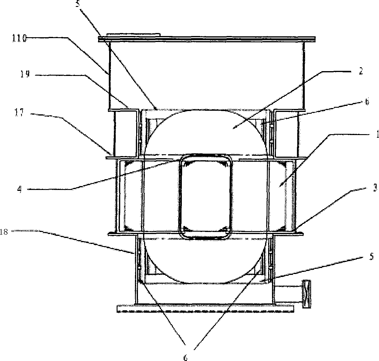
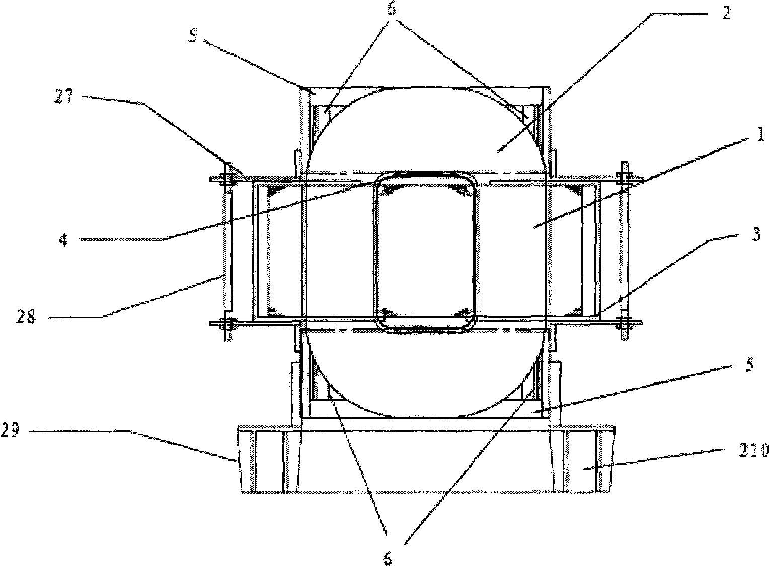
[0031] figure 1 It is the first embodiment of the present invention: a shell-type amorphous alloy transformer with an oil tank or an air tank. Here, the transformer oil tank can be transformer oil or high temperature resistant oil; if gas insulation is used, the gas tank can be sulfur hexafluoride gas, or fluorocarbon gas, or inert gas, or compressed air, or nitrogen, or carbon dioxide gas, etc. .

[0032] Such as figure 1 As shown, the amorphous alloy shell core 1 of this embodiment is formed by winding an amorphous alloy strip, and has a rectangular cross section. The structure of the amorphous alloy shell core 1 can be Figure 4 The common three-phase shell-type iron core structure shown, that is, the iron core columns are connected in series in the three-phase windings, and the iron yoke between the phase windings has only one magnetic ...


PUM


Abstract

A body of a shell type amorphous alloy transformer comprises an amorphous alloy shell type iron core (1) and rectangular coils which are alternatively arranged, and a U-shaped epoxy resin insulating clamp (3) is arranged outside an iron yoke (31) of the amorphous alloy shell type iron core (1). Square type frameworks (5) are respectively arranged on the upper portion and the lower portion of the iron core (5) outside each phase winding (2), and the phase winding is clamped by the square type frameworks (5) through an insulating plate (6). An intermediate section of box body and a lower section of box body in a transformer with an oil box or a gas box can stretch the square type framework (5) of each phase winding through a breast beam and box walls, thereby facilitating the short-circuit force of the phase winding to transfer to the square type framework (5) and the oil box walls. A coil support plate (4) which is formed by insulating elements is arranged on the inner side of the phase winding (2), which can lead the crosswise force of a coil not to press the amorphous alloy shell type iron core (1) when the coil is in short-circuit. The intermediate section of box body and the lower section of box body are used to position the iron core through the U-shape clamp (3). A dry transformer is used to fix the iron core (1) through an upper location press plate and a lower location press plate (27).

Description

technical field [0001] The invention relates to a body of a shell type amorphous alloy transformer. Background technique [0002] Amorphous alloy transformer is an excellent low-loss energy-saving transformer. It uses amorphous alloy materials instead of silicon steel sheets to make iron cores. It is characterized by low no-load loss and small no-load current, so it has received more and more attention. Pay attention to. However, since amorphous alloy materials are very sensitive to mechanical stress, both tensile stress and bending stress will affect their magnetic properties. Therefore, the short-circuit resistance of the amorphous alloy transformer is poor, and the iron core cannot bear the action of mechanical force. [0003] The current amorphous alloy transformer generally adopts the core transformer structure, the high and low voltage coils are concentrically set on the core column, and the coil surrounds the core. When the core transformer structure is subjected t...

Claims


Application Information

Patent Timeline
IPC IPC(8): H01F27/30H01F27/28H01F27/02H01F27/26
Inventor 张国强王新牛文豪
Owner INST OF ELECTRICAL ENG CHINESE ACAD OF SCI
Why Eureka
Try Eureka