Powder-spraying device for producing low-light-level image intensifier luminescent screen powder-layer

A low-light image intensifier and fluorescent screen technology, which is applied to the device and coating of the surface coating liquid, can solve the problems of difficulty in controlling the amount of powder, waste of fluorescent powder, and poor effect of dusting on the filter. Achieve the effect of overcoming agglomeration and saving raw materials

Inactive Publication Date: 2009-03-25
CHINA NORTH IND NO 205 RES INST
View PDF1 Cites 8 Cited by
  • Summary
  • Abstract
  • Description
  • Claims
  • Application Information

AI Technical Summary

Problems solved by technology

Although the above two measures have also achieved certain results, some problems still occur in actual work: for example, the fluorescent powder that has been sorted and screened will not agglomerate in a short period of time, but after After a period of time, the fluorescent powder will appear agglomerated again, which cannot fundamentally solve the problem; the effect of dusting the filter on the bottle mask is not very good, because it is difficult to control the amount of powder when pouring the powder from the bottle, or due to filtration The clogging of the net prevents the phosphor from being poured out, or pours out a lot at once when the force is large, which will either affect the work efficiency or cause waste of the phosphor
In addition, in actual work, dusting by hand with a bottle with a filter does not guarantee the uniformity of the dusting

Method used


Image

  • Powder-spraying device for producing low-light-level image intensifier luminescent screen powder-layer
  • Powder-spraying device for producing low-light-level image intensifier luminescent screen powder-layer

Examples


Embodiment Construction

[0015] The present invention will be further described in detail below in conjunction with the accompanying drawings and preferred embodiments.

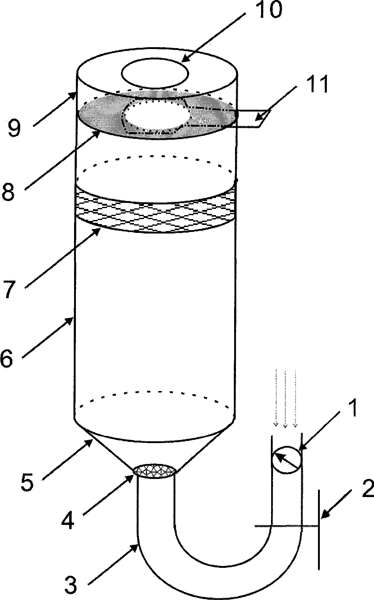
[0016] as figure 1 As shown, the preferred embodiment of the powder spraying device of the present invention is composed of an air intake assembly, a powder spraying chamber 6 and a fluorescent screen fixture 9 . The intake assembly includes a pressure reducing valve 1, a solenoid valve 2, a U-shaped pipe 3 made of stainless steel, a first filter screen 4, and a frustum-shaped shell seat 5 made of stainless steel. The internal diameter of U-shaped pipe 3 is 5~10mm, and its one end is connected with the small mouth end of conical shell seat 5 and the first filter screen 4 is housed in the connection position, and the other end is air inlet then installs decompression valve 1 and electromagnetic valve 2. The powder spraying chamber 6 is a glass cylinder, and its inner diameter and height can be determined according to the area of ​​t...


PUM


Abstract

The invention discloses a powder spray device used to make a fluorescent screen powder layer of a low-light-level image intensifier, which comprises an air inlet component including a truncated cone-shaped shell seat, a filtering net, a U-shaped pipe, an electromagnetic valve and a pressure reducing valve, a powder spraying chamber with an air hole, and a fluorescent screen jig with a movable baffle, wherein, the big end and the small end of the truncated cone-shaped shell seat are respectively connected with the lower end of an air jet chamber and the U-shaped pipe, the pressure reducing valve and the electromagnetic valve are sequentially arranged at the other end of the U-shaped pipe, and the fluorescent screen jig is disposed at the upper end of the powder spraying chamber. When in use, the fluorescent screen is placed on the fluorescent screen jig, gases passing through the pressure reducing valve can enter the powder spraying chamber by a pulse mode through the on / off alternating state of the electromagnetic valve under the condition of closed movable baffle, so as to disperse the agglomerated fluorescent powder; and the dispersed fluorescent powder is sprayed on a glue layer of the fluorescent screen evenly under the function of continuous air flow by opening the movable baffle and making the electromagnetic valve be in the open state. The invention solves the problems of bulge points on the powder layer due to agglomeration of fluorescent powder and uneven manual powder dusting.

Description

technical field [0001] The invention belongs to the technical field of photoelectric imaging, and mainly relates to a fluorescent screen of a low-light image intensifier, in particular to a powder spraying device for making a powder layer of the fluorescent screen. Background technique [0002] There are many methods for making the powder layer of the fluorescent screen of the low-light image intensifier, mainly divided into precipitation method, centrifugation method, brushing method, electrophoresis method, spraying method and so on. Different manufacturing methods are suitable for slightly different fluorescent screen objects. The precipitation method is suitable for the production of large-area fluorescent screen powder layers, the centrifugal method is only suitable for the production of small-area fluorescent screen powder layers, the brush coating method has wide applicability and can be used for the production of fluorescent screen powder layers of different sizes, a...

Claims


Application Information

Patent Timeline
Patent Type & Authority Applications(China)
IPC IPC(8): B05C19/04B05C19/06B05C13/02
Inventor 刘照路张太民刘晓健聂晶
Owner CHINA NORTH IND NO 205 RES INST
Why Eureka
Try Eureka