
Hydraulic control system for stepless brake retarder

A technology of hydraulic control system and reducer, which is applied in the direction of track brakes, railway car body parts, transportation and packaging, etc. It can solve the problems that restrict the development of hump speed regulation technology, the balanced braking method cannot be realized, and the reducer cannot be adjusted. Achieve the effect of braking force generation and soft change, reducer and speed change smoothly, and ease speed increase

Active Publication Date: 2009-03-25
西安优势铁路新技术有限责任公司
View PDF1 Cites 7 Cited by
  • Summary
  • Abstract
  • Description
  • Claims
  • Application Information

AI Technical Summary

Problems solved by technology

To sum up, it can be seen that: at present, the existing reducers in China, whether it is a clamp type reducer or a non-clamp type reducer, except for the TJDY graded brake reducer that can achieve three-level braking force, the rest of the reducers The braking force cannot be adjusted, on the one hand, the control accuracy is low, on the other hand, it restricts the development of hump speed regulation technology, that is, the "balanced braking method" cannot be realized

Method used


Image

  • Hydraulic control system for stepless brake retarder
  • Hydraulic control system for stepless brake retarder
  • Hydraulic control system for stepless brake retarder

Examples


Embodiment Construction

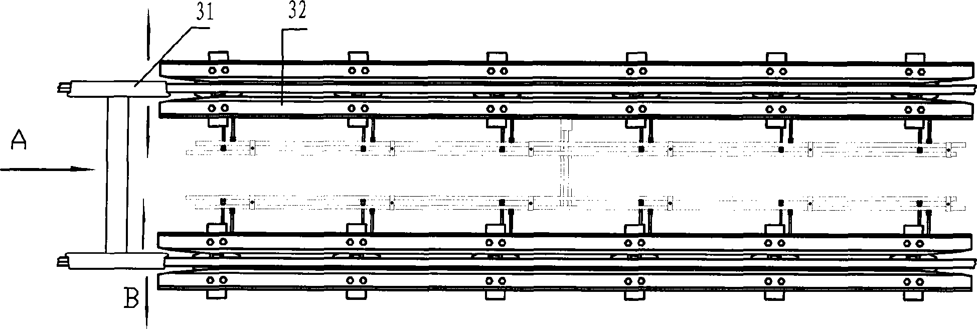
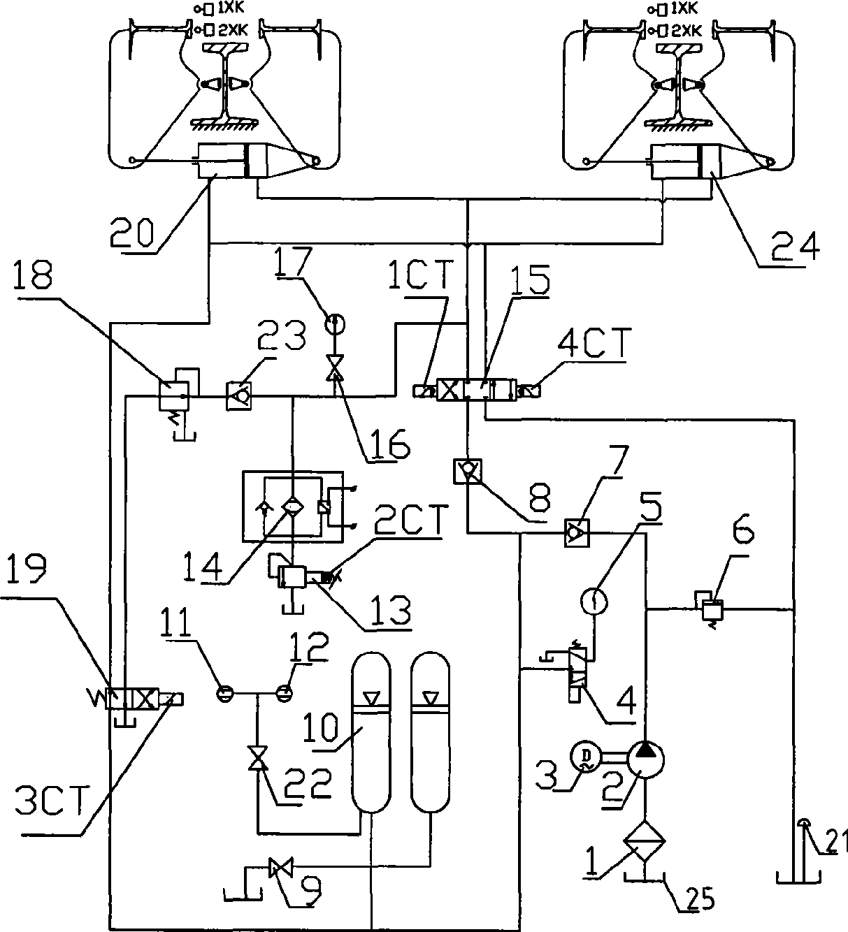
[0024] see figure 1 , the working principle of the present invention is as follows:

[0025] Driven by the hydraulic system, the actuator moves to the braking position. When the vehicle slides down from the hump along the A direction and enters the reducer (working position), it will squeeze the brake rail 32 along the B direction, and the cylinder brake chamber 24 The oil pressure is compressed, and the pressure rises. The pressure is transmitted to the brake rail 32→wheel 31 through the brake chamber 24 of the oil cylinder in turn, and the friction torque is applied to the wheel 31 through the brake rail 32 to brake the vehicle. Since the system pressure is directly proportional to the braking force, adjusting the system pressure will change the braking force.

[0026] The generation of braking force and the force of hydraulic pressure reacting on the wheels come from: wheels 31 brake rail 32 The hydraulic cylinder brake chamber 24 realizes the interaction of braking fo...


PUM


Abstract

The invention relates to a hydraulic control system of a stepless brake speed reducer, which comprises an oil tank, an oil cylinder, an oil pump which is driven by a motor and an energy accumulator, and is characterized in that: the hydraulic control system of the stepless brake speed reducer further comprises a first reversing valve, a second reversing valve, a pressure reducing valve, a first one-way valve, a second one-way valve, a third one-way valve and a proportional valve; the oil pump is accessed to the energy accumulator through the first one-way valve, the energy accumulator is communicated with a relief cavity of the oil cylinder through the second one-way valve and the first reversing valve sequentially; one end of the second reversing valve is accessed to the oil tank, the other end is accessed to a brake cavity of the oil cylinder through the pressure reducing valve and the third one-way valve sequentially; the oil tank is accessed to the oil pump, the energy accumulator is accessed to the oil tank; the brake cavity of the oil cylinder is accessed to the oil tank through the first reversing valve; and the relief cavity of the oil cylinder is accessed to the oil tank through the proportional valve. The hydraulic control system of the stepless brake speed reducer realizes the stepless speed regulation, has rapid repeated brake response, strong adaptability and no impact on a vehicle and is conductive to prolonging the service life of the vehicle and the device.

Description

technical field [0001] The invention relates to a vehicle brake control system, in particular to a hydraulic control system of a stepless brake reducer. Background technique [0002] At present, the reducers used for the braking of hump automation in my country can be divided into two types according to the braking principle: one is the clamp type reducer, and the other is the non-clamp type reducer. [0003] The clamp-type reducer can implement different braking forces for vehicles with different loads through floating rails, but the disadvantage is that it cannot implement different braking forces for vehicles with the same load, that is, the braking force is single and cannot be adjusted, so the control accuracy is low. Unable to achieve balanced braking. [0004] The disadvantages of the controllable roof in the non-clamp type reducer are the large number, small braking force, low design speed, inability to realize "putting the head and blocking the tail", and low decod...

Claims


Application Information

Patent Timeline
IPC IPC(8): B61K7/08
Inventor 孙长征晁中叶陈森盛于秋玲
Owner 西安优势铁路新技术有限责任公司
Learn More