Bionics machine acaleph driven by shape-memory alloy wire

A technology of memory alloy wire and machine, which is applied in the direction of non-rotating propulsion elements, etc., can solve the problems of complex structure and different action principles of machine bionic jellyfish, and achieve the effect of good bionic effect, large action range and simple structure

Inactive Publication Date: 2009-03-25
HARBIN INST OF TECH
View PDF1 Cites 45 Cited by
  • Summary
  • Abstract
  • Description
  • Claims
  • Application Information

AI Technical Summary

Problems solved by technology

[0012] The purpose of the present invention is to provide a bionic jellyfish driven by a shape memory alloy wire, which can solve the problem that the existing bionic jellyfish only simulates the action of the jellyfish, does

Method used


Image

  • Bionics machine acaleph driven by shape-memory alloy wire
  • Bionics machine acaleph driven by shape-memory alloy wire
  • Bionics machine acaleph driven by shape-memory alloy wire

Examples


specific Embodiment approach 1

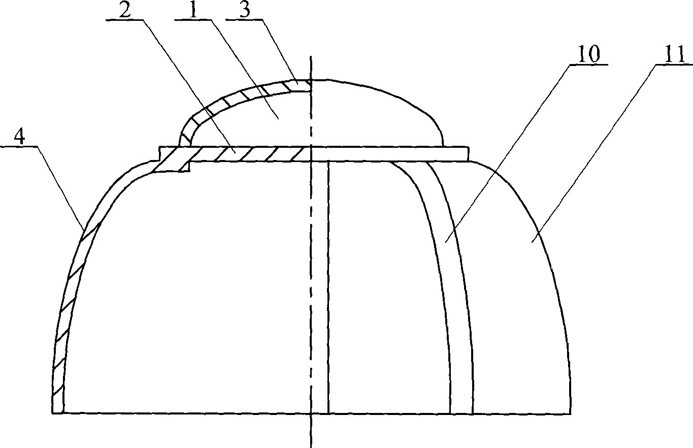
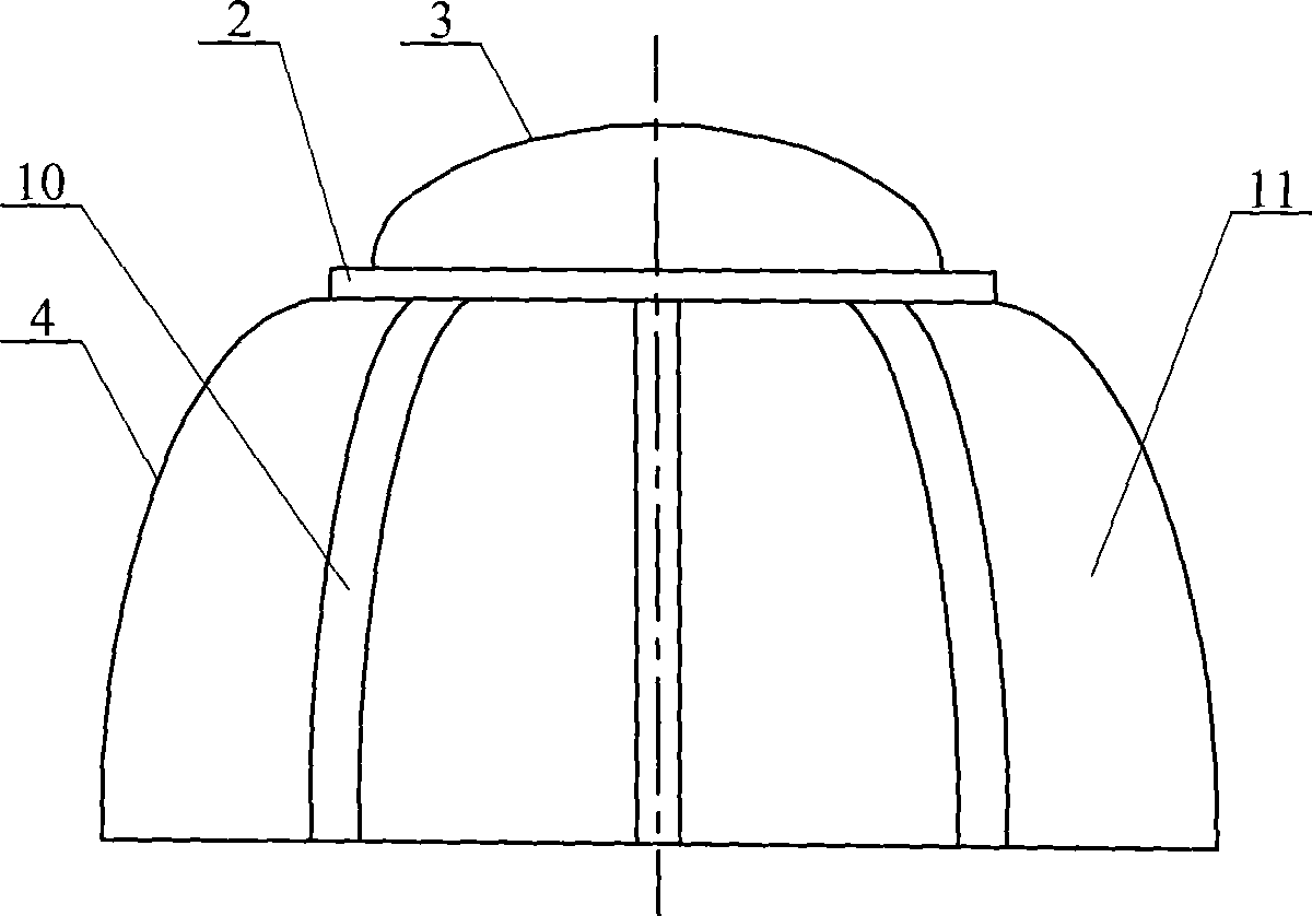
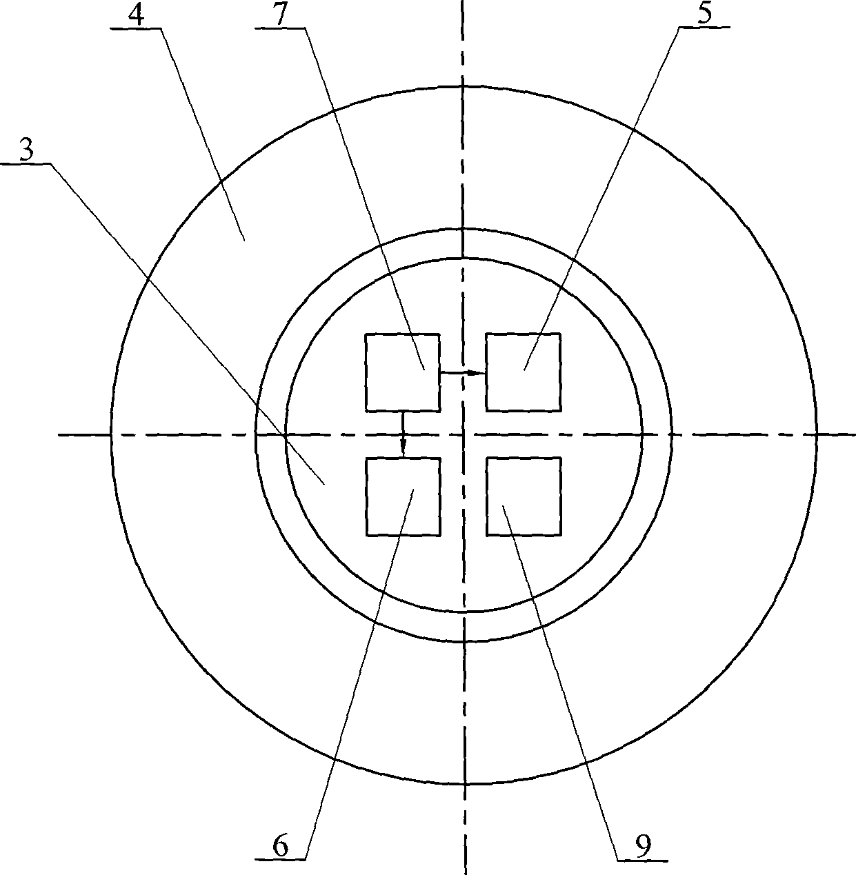
[0016] Specific implementation mode one: combine Figure 1 to Figure 12 Describe this embodiment, this embodiment is made up of upper chamber body 1, umbrella body 4, control device 5, communication device 6, power supply 7 and ups and downs control device 9; Said upper chamber body 1 is made up of support body 2 and sealing cover 3 , the umbrella body 4 is composed of an umbrella-shaped flexible layer 11 and at least three action units 10, the at least three action units 10 are uniformly distributed along the circumferential direction of the support body 2, and each action unit 10 is formed by a shape Memory alloy wire 12, elastic body 13, skin 15 and matrix 16, the upper end of the inner surface of each elastic body 13 is fixed with matrix 16, and each elastic body 13 is closely attached to the inner surface and fixed with shape memory alloy wire 12. The two ends of the shape memory alloy wire 12 are fixed on the base 16, and each action unit 10 is wrapped in the umbrella-sh...

specific Embodiment approach 2

[0025] Specific Embodiment 2: This embodiment is described with reference to Fig. 4, Fig. 7, Fig. 9 and Fig. 10. The shape memory alloy wire 12 of this embodiment is U-shaped, and the two sides of the base 16 and the U-shaped shape memory alloy wire 12 are A through hole 17 is respectively provided at the corresponding position of the end, and the shape memory alloy wire 12 is respectively connected to the output end of the power supply through the wire 14 passing through the two through holes 17 on the base body 16 . The U-shaped shape memory alloy wire 12 can ensure a larger contact area between the shape memory alloy wire 12 and the elastic body 13 . Other components and connections are the same as those in the first embodiment.

specific Embodiment approach 3

[0026] Specific Embodiment Three: This embodiment is described in conjunction with Fig. 9 and Fig. 10. The elastic body 13 of this embodiment is an elastic sheet or an elastic sheet, and the elastic sheet or elastic sheet is made of an insulating material or a metal material. When the elastic sheet is a metal Insulation treatment must be done between the shape memory alloy wire 12 and the elastic body 13. The cross-section of the shape memory alloy wire 12 is circular, square or rectangular, and the elastic body 13 is in the shape of a flat strip, which can be bent at different angles or straight according to the overall shape of the jellyfish, so as to ensure that the shape memory alloy wire 12 Fit tightly on the elastic body 13. Other components and connections are the same as those in the first embodiment.


PUM


Abstract

The invention discloses a biomimetic mechanical jellyfish that is driven by shape memory alloy wires, relates to a biomimetic mechanical jellyfish and aims at solving the problems that the existing biomimetic mechanical jellyfishes only simulate jellyfish actions, do not cover devices such as a drive device and the like, and have complex structure and the biomimetic effect that is totally different with the action principle of real jellyfishes. The biomimetic mechanical jellyfish has following structure: an action unit (10) consists of the shape memory alloy wires (12), an elastic body (13), a coating skin (15) and a substrate (16), the substrate (16) and the shape memory alloy wires (12) are fixedly arranged on the elastic body (13), the action unit (10) is coated inside an umbrella-like soft layer (11), the coating skin (15) covers outside the shape memory alloy wires (12), the substrate (16) and a sealing cover (3) are fixedly connected with a supporting body (2), a power source (7), a control device (5), a communication device (6) and a sinking and floating control device (9) are fixedly arranged on the supporting body (2), and the power source (7) provides electricity respectively to the control device (5), the communication device (6) and the shape memory alloy wires (12). The biomimetic mechanical jellyfish has simple structure, lightness, low production cost, large action range and good biomimetic effect.

Description

technical field [0001] The invention relates to a bionic robot jellyfish. Background technique [0002] Underwater propulsion is a relatively energy-intensive mode of transport, since the thrusters must overcome high water resistance. The current main mode of surface transportation is still propeller propulsion, but this propulsion mode has its obvious disadvantages. First of all, the propulsion efficiency is not high, and the propeller propulsion also produces useless torque while generating thrust; secondly, the cavitation phenomenon that occurs due to the pressure difference between the blade back and the blade surface when the propeller rotates at a high degree causes the hull and blades to vibrate and erode , making a lot of noise. For this reason, people invented the water jet propulsion device, and obtained greater development in practical application. A common water jet propulsion device generates thrust through a propulsion pump, and uses the reaction force of th...

Claims


Application Information

Patent Timeline
IPC IPC(8): B63H1/30
Inventor 王振龙李健杭观荣王扬威
Owner HARBIN INST OF TECH
Why Eureka
Try Eureka