Engine braking apparatus and method using single valve and bridge of valve

A technology for engine braking and engine application in the direction of valve drive devices, valve devices, engine components, etc., which can solve problems such as failure to work normally, reduced braking performance, asymmetrical loads, etc., to eliminate asymmetrical loads and reduce braking load, effect of reducing complexity

Active Publication Date: 2009-03-25
SHANGHAI UNIVERSOON AUTOPARTS CO LTD
View PDF5 Cites 34 Cited by
  • Summary
  • Abstract
  • Description
  • Claims
  • Application Information

AI Technical Summary

Problems solved by technology

If resetting occurs too quickly, the brake valve lift is lost too much (lower valve lift and early valve closing), reducing braking performance
If the reset happens too late, the brake valve will not be able to close before the main valve action begins, causing an asymmetrical load
Therefore, the rocker integrated brake of the '730 patent may not work properly at high engine speeds because the reset time and height are very small and the load or pressure on the reset

Method used


Image

  • Engine braking apparatus and method using single valve and bridge of valve
  • Engine braking apparatus and method using single valve and bridge of valve
  • Engine braking apparatus and method using single valve and bridge of valve

Examples


Embodiment 1

[0079] Figures 3A and 3B are schematic views of the first embodiment of the engine braking device of the present invention in its "OFF" and "ON" positions. The figure includes three main parts: the drive mechanism 100 for engine braking, the exhaust valve actuator 200 and the exhaust valve 300 . The exhaust valve actuator 200 includes a cam 230 , a rocker arm 210 , and an exhaust lash adjustment system. The cam 230 has a large raised portion 220 on the inner base circle 225 (relative to the smaller raised portion used for braking later) for normal operation of the engine. The rocker arm 210 is swingably mounted on the rocker shaft 205, with a cam follower 235 at one end, and a valve gap adjusting screw 110, a valve gap adjusting piston 112 and an elephant foot pad 114 at the other end of the exhaust valve gap adjusting system. . The valve gap adjusting screw 110 is fixed on the rocker arm 210 by the lock nut 105 . A spring 198 can be installed on the valve gap adjusting scr...

Embodiment 2

[0086] Figure 4 is a schematic view of a second embodiment of the engine braking device of the present invention in its "on" position. In this embodiment, a brake valve actuator and a brake reset mechanism 150 are added on the basis of the first embodiment. The brake valve actuator is integrated in the exhaust valve actuator 200 of the engine. In addition to the brake valve gap adjustment system, it also contains at least one small cam lobe for braking (this embodiment contains two small cam lobe portions 232 and 233). The small cam lobe portions 232 and 233 and the large cam lobe portion 220 of the engine are integrated on the existing engine cam 230 . In order to get over the small cam lobe portions 232 and 233 during normal engine operation, the large cam lobe portion 220 must be enlarged. The brake reset mechanism 150 is used to modify the valve lift curve generated by the increased large cam lobe 220 . Brake reset mechanism 150 is integrated with drive mechanism 100 . ...

Embodiment 3

[0091] Figure 5 is a schematic view of a third embodiment of the engine braking device of the present invention in its "on" position. This embodiment has a different brake reset mechanism 150 from the second embodiment. The brake reset piston 165 of the brake reset mechanism 150 is slidably disposed within the valve bridge 400 directly below the elephant foot pad 114 . The drain hole 197 on the brake piston 160 is replaced by a drain channel 167 in the valve bridge 400 . The spring 198 of the detent biases the exhaust valve actuator 200 with the reset piston 165 against the valve bridge 400 .

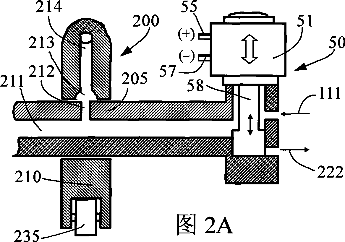
[0092] When engine braking is required, the engine braking control mechanism 50 is turned on (FIG. 2A). The fluid passes through the brake fluid network, including the fluid channels 113 and 115 in the slack adjustment screw 110, the fluid channel 197e in the reset piston 165, and the channel 412 in the valve bridge 400, and pushes open the one-way shut-off valve 170, from the valve ...


PUM


Abstract

The invention discloses an engine braking device (engine retarder) and an engine braking method for using a single valve and a valve bridge. A driving mechanism of the device comprises a braking hydraulic system integrated in an exhaust valve system as well as a braking bearing system and a brake valve actuator which are integrated in an exhaust valve actuator of an engine. The braking hydraulic system comprises a braking piston arranged in the valve bridge. The device also comprises a control mechanism used to control the piston to move between the non-operating position and the operating position. At the non-operating position, the braking piston retracts for braking the normal separation of the driving mechanism and the engine; at the operating position, the braking piston extends out for braking the driving mechanism to open one of two exhaust valves to produce the braking operation of the engine. The braking device uses a simple and reliable reset mechanism, reduces or even eliminates asymmetrical load produced by the braking of the single valve, does not increase the height and the weight of the engine, reduces elements and the complexity, reduces manufacturing cost, and improves the reliability of a system.

Description

technical field [0001] This invention relates to internal combustion engine braking, and more particularly to an apparatus and method for switching the engine from normal operation to braking operation. Background technique [0002] It is well known to use an internal combustion engine as a means of braking, simply by temporarily converting the engine to a compressor. This conversion can be achieved by cutting off fuel, opening the exhaust valve at or near the end of the engine piston's compression stroke, allowing the compressed gas (usually air) to be released, and the energy absorbed by the engine to compress the gas during the compression stroke, It cannot be returned to the engine piston during the subsequent expansion or "power" stroke, but is dissipated through the engine's exhaust and cooling system. The end result is efficient engine braking. [0003] Engine braking is necessary for internal combustion engines, especially compression ignition engines, also known a...

Claims


Application Information

Patent Timeline
IPC IPC(8): F01L13/06
CPCF01L13/065F01L1/08F01L1/181F01L1/267
Inventor 杨洲
Owner SHANGHAI UNIVERSOON AUTOPARTS CO LTD
Why Eureka
Try Eureka